# Getting Started
This section covers the fundamental steps for preparing your PIR Sensor for use — including powering, connecting, mounting, and aiming the unit. It guides you through initial setup so you can quickly get the sensor operational and ready for deployment in the field.
# Powering Your Sensor
The Camtraptions PIR Sensor v4 can be powered in several different ways, offering flexibility for a wide range of field conditions and setup durations.
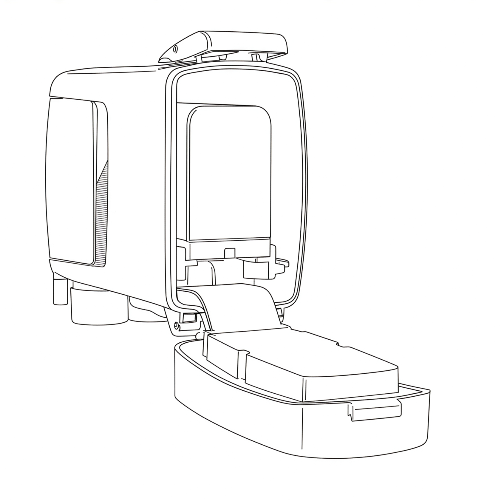
#### **1. NPF-Type Rechargeable Battery**
The primary power option is a **Sony-type NP-F lithium-ion battery**, a widely available and reliable standard used across the photographic industry. The PIR v4 is compatible with NP-F batteries up to the size of an NP-F970 and with a maximum height of 60mm. Note that some third-party manufacturers produce NP-F batteries with built-in USB-charging ports that exceed this height and will not fit inside the sensor.
NP-F batteries are **sold separately**, as they are easy to source locally from most camera or video equipment suppliers. Place the battery into the battery tray, about 1cm away from its fully engaged position. Apply slight downward force to ensure that the central locking tab in the battery tray is fully depressed and, at the same time, push the battery forward until it clicks into place.
To remove the battery, simply pull it backwards.
#### **2. AA Battery Adapter**
As an alternative, the sensor can be powered using **six AA batteries** installed in a **6xAA to NP-F battery adapter** (sold separately). The adapter fits into the same mounting slot as the NP-F battery. This option provides flexibility in situations where rechargeable lithium batteries are not available or convenient to use.
To install, insert the adapter in the same way as an NP-F battery, ensuring it is seated securely before closing the rear door. The individual AA cells may be removed/inserted while keeping the adapter in-situ inside the PIR v4, or alternatively the entire adapter can be removed in the same way as an NP-F battery.
#### **3. External DC Power Input**
For extended deployments or fixed installations, the sensor can also be powered via the **DC input jack** located on the underside of the unit. The sensor accepts **DC input voltages from 4V to 12V**.
For added reliability in the field, the sensor is compatible with **Camtraptions Waterproof Screw-lock DC connectors**, which provide a more secure and weather-resistant connection.
Ensure that any **internal battery** is **removed** from within the PIR v4 before an **external battery** or power source is connected to the sensor. Internal batteries cannot be connected and used at the same time as an external power supply. The only exception to this is if you are connecting a small external solar panel to trickle charge 6x Ni-MH AA batteries inside the PIR v4.
# Connecting Your Camera
The Camtraptions PIR Sensor v4 can trigger your camera in two ways: **wirelessly** or via a **wired connection**. Both methods are compatible with DSLR and mirrorless cameras that feature an external shutter-release socket.
#### **1. Wireless Connection (Default)**
The sensor includes a built-in **wireless transmitter** that communicates with **Camtraptions Wireless Receivers**. This is the simplest and most flexible way to set up your camera trap.
- The wireless transmitter is **enabled by default** and set to **Channel 1**.
- You can change the channel via the [**Wireless Channel**](https://docs.camtraptions.com/books/pir-v4-manual/page/wireless-channel "Wireless channel") screen in the sensor’s menu.
- Up to **15 channels** are available, corresponding directly with the 15 channels available on Camtraptions Wireless Receivers.
To establish a connection:
1. Ensure the **wireless channel** on the sensor matches the **channel setting** on your wireless receiver.
2. Plug the **wireless receiver** into your camera’s **shutter-release socket** using the appropriate **Camtraptions camera connecting cable**.
The wireless transmitter can be **disabled** in the menu if you prefer to operate the sensor via a wired connection.
#### **2. Wired Connection**
Alternatively, the sensor can be connected directly to the camera using a **wired cable**.
- The camera output socket is located on the **underside** of the sensor and protected by a **weather-sealing rubber bung**.
- Use the **Camtraptions Screw-lock Waterproof Cable for PIR Sensor v4** to connect the sensor to your camera’s shutter-release socket. Ensure that the black silicone sealing band on the waterproof cable's connector jack is seated evenly around the connector barrel. Plug in the cable and screw on the locking nut to fasten. **Do not over-tighten the cable's locking nut** - excessive force is not required to make a good seal.
A robust and highly reliable direct connection is now created between the sensor and the camera.
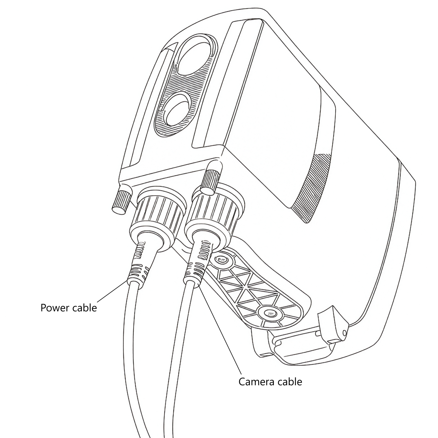
A standard **Camtraptions camera connecting cable** or **sensor extension cable** can also be plugged into the sensor, but using these basic cables instead of the dedicated waterproof cable system will void the warranty of the PIR Sensor v4, as its weather-sealing will not be maintained.
##### **Waterproof Cable Connection Tips**
- Even if only one of the waterproof connection types is being utilised, e.g. camera trigger signal output and not the external power input - it is recommended to securely fit **both ends** of the Screw-lock Waterproof Cable to the PIR v4. This ensures both of the sensor's ports and the cable's connectors are sealed against moisture and dirt, maintaining complete weather protection for the sensor and cable.
- If access is restricted, removing the side flap and thumbscrew can make it easier to tighten or loosen the cable nut securely.
- Additional Camtraptions Waterproof Cables and adapters will be necessary to complete the connection to the camera.
#### **3. Choosing Between Wireless and Wired**
Both connection types have advantages, depending on your setup requirements:
| **Connection Type** | **Advantages** | **Considerations** |
|---|
| **Wireless** | Fast and simple setup. No long cables between camera and sensor, allowing greater flexibility in positioning. Reduces risk of cables being pulled, damaged, or chewed by animals. | Wireless receiver consumes additional power, impacting total standby time of the setup. |
| **Wired** | Very power-efficient. Does not require a powered receiver. Immune to wireless interference and blocked or weak wireless signals. | Requires a physical cable connection, limiting placement flexibility and adding potential for cable damage or disturbance. |
In most cases, the **wireless setup** is preferred for its simplicity and flexibility, particularly when the sensor needs to be positioned several metres away from the camera. However, a **wired setup** is ideal when power efficiency is the priority or when the sensor and camera are mounted close together.
Camtraptions Wireless Receivers are designed for **exceptional energy efficiency**, making long-term wireless setups (lasting weeks or even months) possible when paired with larger batteries or solar power systems.
# Mounting Your Sensor
The Camtraptions PIR Sensor v4 features **two tripod sockets** on the underside, providing flexible and secure mounting options for a wide range of setups.
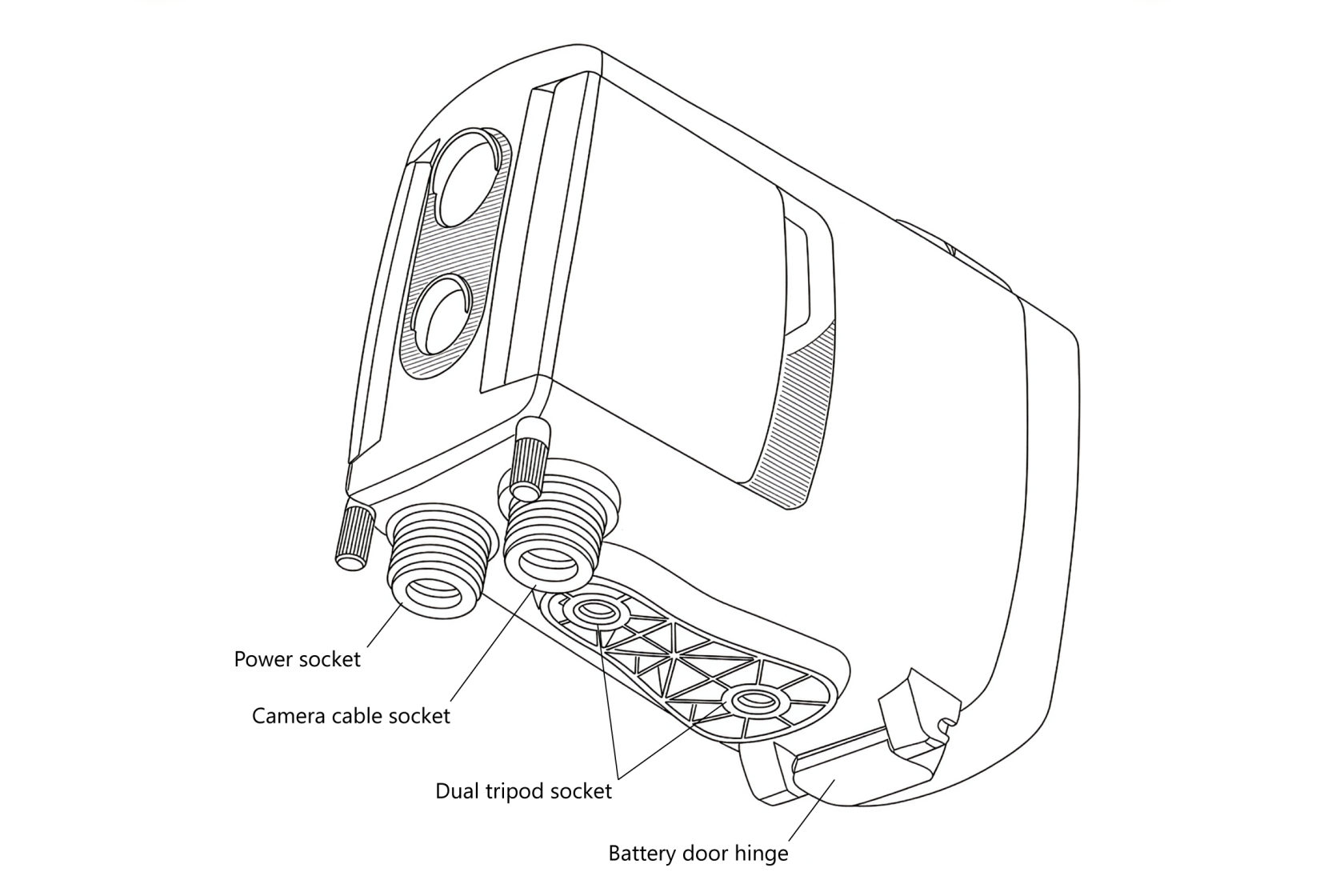
#### **Single-Screw Mounting**
For simple installations—such as when using a **MightyPod** or a **third-party tripod**—the sensor can be mounted using just **one tripod socket**.
#### **Dual-Screw Mounting**
For the most secure and stable mounting, particularly in outdoor or long-term deployments, a **dual-screw setup** can be used.
This prevents the sensor from twisting or shifting during installation or use. The **socket spacing** matches the standard used by the **Camtraptions Jungle Mount System**, enabling the sensor to be mounted on:
- The ground
- Posts or poles
- Tree limbs or trunks
This system provides a robust, flexible solution for positioning the sensor in almost any environment.
When selecting a mounting method, ensure that the chosen mount **does not obstruct the rear door** of the sensor when it is opened. If the mount prevents the door from opening fully, forcing it may damage the hinge. Always allow sufficient clearance for the door to open freely for battery changes.
# Controlling the Field of View
The **field of view (FOV)** of the Camtraptions PIR Sensor determines **where an animal will be when the camera is triggered**, making it a crucial part of composing your images—particularly for still photography. The field of view can be adjusted in several ways to precisely control the trigger zone.
#### **1. Using the Adjustable Side Flaps**
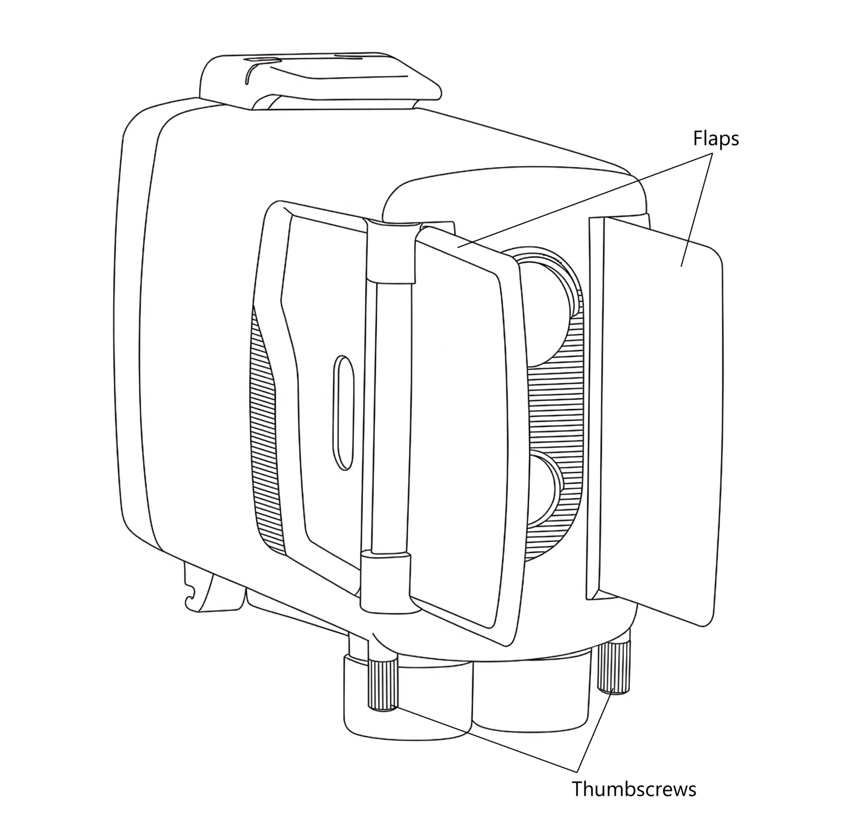
Each side of the sensor is fitted with a **flap** or **blinker** that can be used to **limit the field of view** of the PIR sensors.
By folding the flaps outward, you can block unwanted detection zones to either side, ensuring that the sensor only triggers when an animal is directly in front of it.
To adjust the flaps:
1. **Loosen the thumbscrew** on each flap.
2. Rotate the flap into the desired position to restrict the field of view as needed.
3. **Tighten the thumbscrew** again to hold the flap firmly in place.
For best results, ensure that both flaps are positioned symmetrically, with the sensor aimed at the **centre of the intended trigger zone**. The PIR elements are most sensitive in the **middle of their field of view**, so symmetrical adjustment helps ensure that the sensor receives the strongest possible signal.
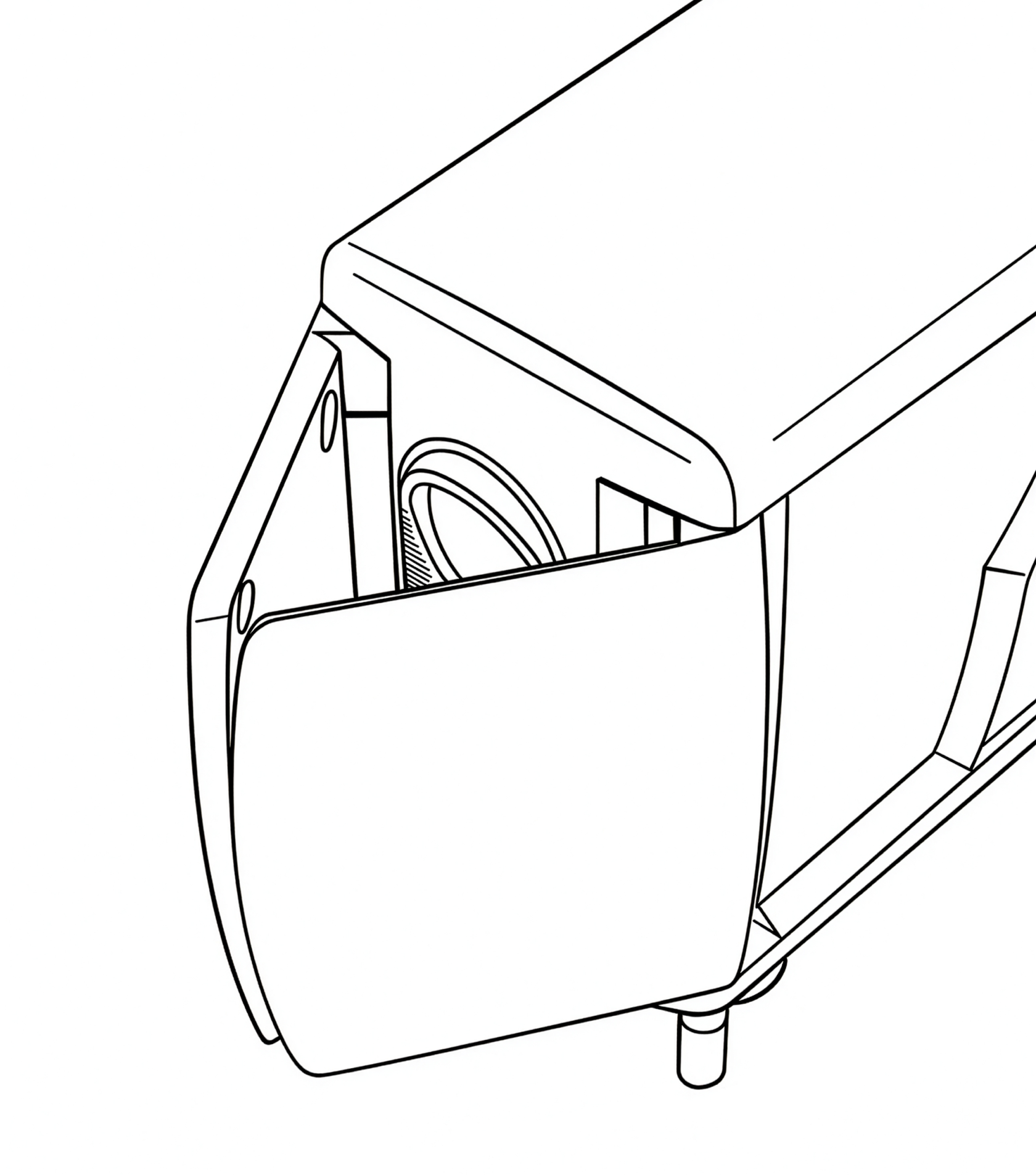
If you would like to **reduce the field of view** even further than the standard side flap positions allow, then you can undo the thumbscrews fully and **swap the left and right flaps** around. This makes it possible to achieve a very narrow angle resulting in an extremely precise trigger area.
Diagram showing flaps in reversed position:
#### **2. Using the Dual-Sensor System**
Version 4 includes **two separate sensors**, each with a different field of view:
- **Wide sensor:** approximately **60° horizontal field of view, 4.5° upward field of view, 13.5° downward field of view** — shorter range but broader coverage.
- **Far sensor:** approximately **10° field of view (horizontal & vertical)** — longer range but more precise detection area.
By adjusting the **relative sensitivity** of these two sensors, or disabling one entirely, you can fine-tune the spread and range of the trigger zone.
It should also be noted that the Wide and Far sensors are both **most sensitive to motion along the horizontal axis** (sideways motion). They are less sensitive to upward/downward motion along the vertical axis.
#### **3. Using the Indicator Light for Setup**
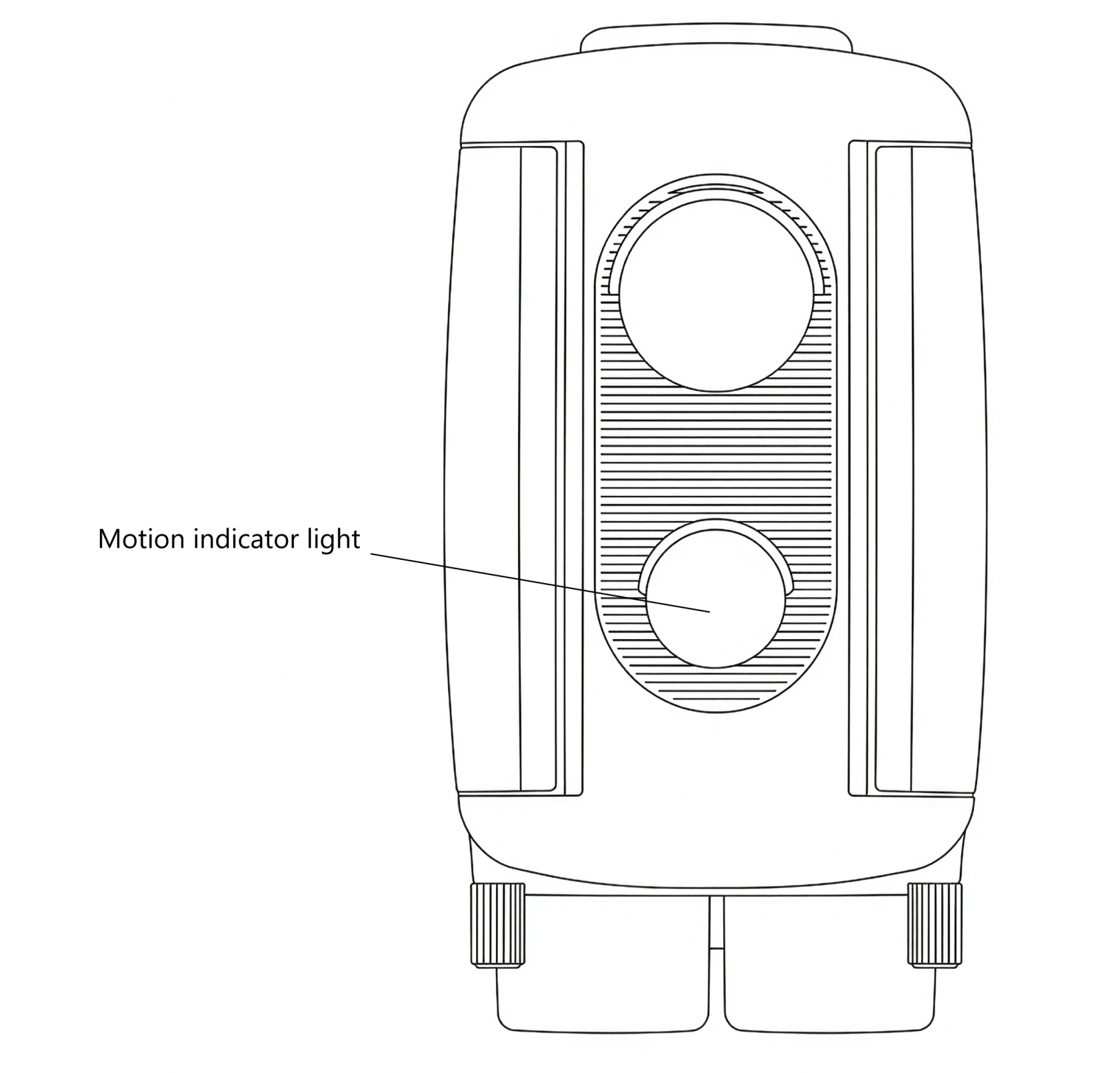
One of the two front sensors includes a **built-in red indicator light** that can assist with setup. When the light is active, it briefly illuminates whenever motion is detected - helping you see exactly where the trigger zone begins and ends.
To use the indicator light:
1. Turn on the sensor or press any button to **activate setup mode**.
2. Walk or wave a hand in front of the sensor to observe **where motion is detected**.
3. Adjust the sensor’s position or flap angles until the trigger zone aligns with your intended composition.
The indicator light remains active for **five minutes** after the last button press, after which it automatically disables to conserve power. For more details, see the [**Indicator Light**](https://docs.camtraptions.com/books/pir-v4-manual/page/front-motion-indicator-light "Front motion indicator light") section later in this manual.
# Turning Your Sensor On and Off
The Camtraptions PIR Sensor v4 has been designed for **maximum reliability in long-term field deployments**. Its power-management system ensures that the sensor automatically recovers from any momentary power interruptions.
#### **Automatic Power-On**
The sensor **automatically turns on** as soon as power is connected.
This behaviour is intentional and provides an important reliability safeguard. If power is ever **momentarily interrupted**—for example, by a brief loss of contact with the battery or vibration in the field—the sensor will automatically restart and resume operation without requiring user input. This ensures that your setup continues functioning even after jolts or disconnections.
#### **Manual Power Control**
Once power is connected, the sensor can be **turned on or off manually** using the **power button** on the rear keypad:
- To **turn on**: Tap the power button and the screen will switch on.
- To **turn off**: Hold the power button again for approximately **two seconds** until the screen shuts down.
#### **Notes on Power Behaviour**
- Because the sensor automatically powers on when a battery is inserted, it may **turn itself on during transport** if jostled or vibrated. This is normal and expected behaviour.
- When used in setups powered from a **central battery** (e.g. a shared DC power supply feeding multiple devices), the sensor will automatically **power back on** when the central power source is reconnected or replaced.
- In **solar-powered systems**, this feature ensures the sensor automatically resumes operation once solar charging restores power after an overnight or cloudy-day power loss.
This design guarantees the **highest possible reliability** in unattended camera-trap installations, ensuring the sensor always returns to active operation when power is restored.
# The Home Screen
When the Camtraptions PIR Sensor v4 is powered on, it will display the **Home Screen**. This is the default screen shown when the sensor is idle and ready to detect motion. The Home Screen provides key information about the sensor’s current operating state at a glance.
#### **Screen Indicators**
The following elements are displayed on the Home Screen:
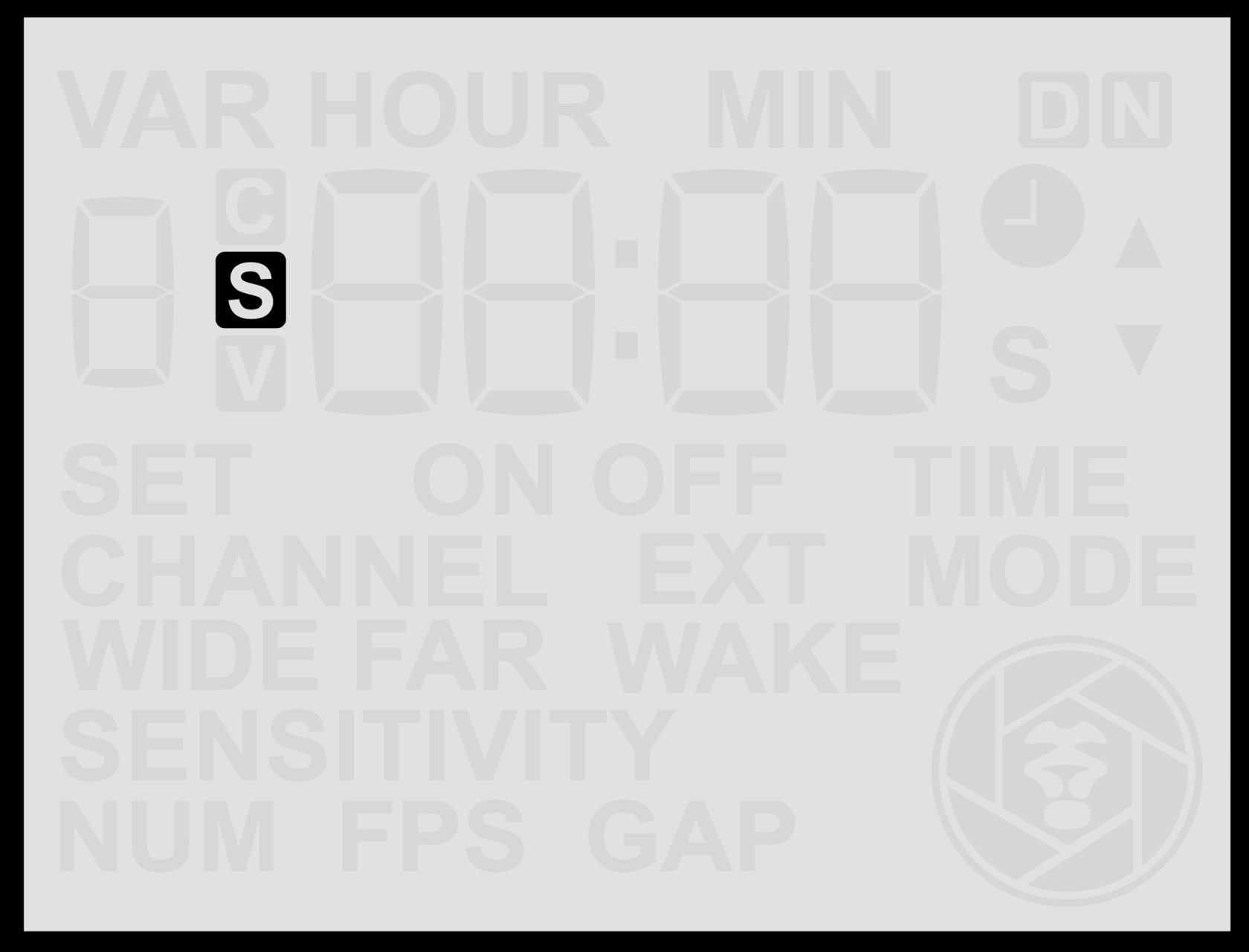
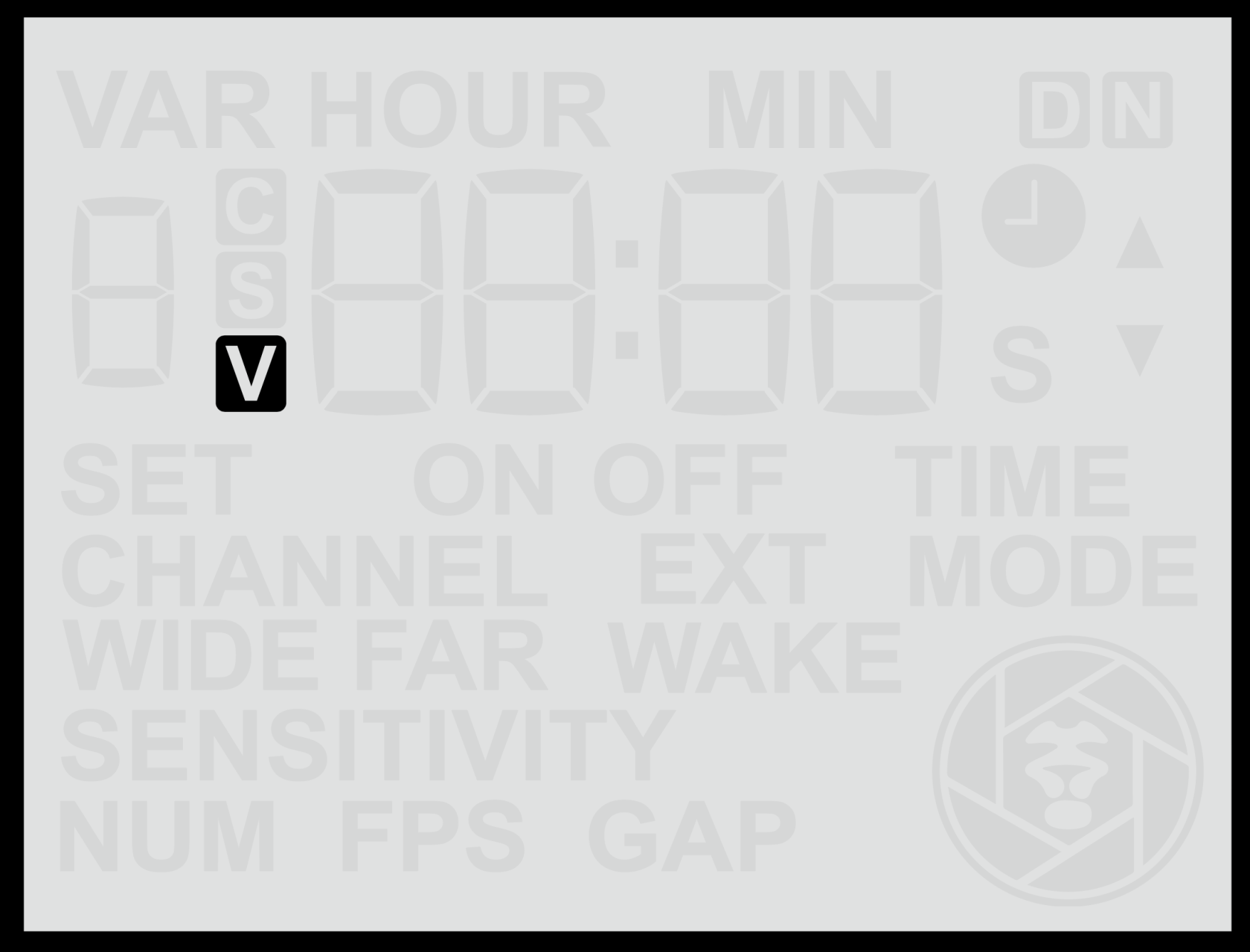
- **S / V Symbol** – Indicates the current **shooting mode**.
- **S** = Still photo mode
- **V** = Video mode
This icon is always visible and lets you confirm at a glance how the sensor will trigger the camera.
|  |  |
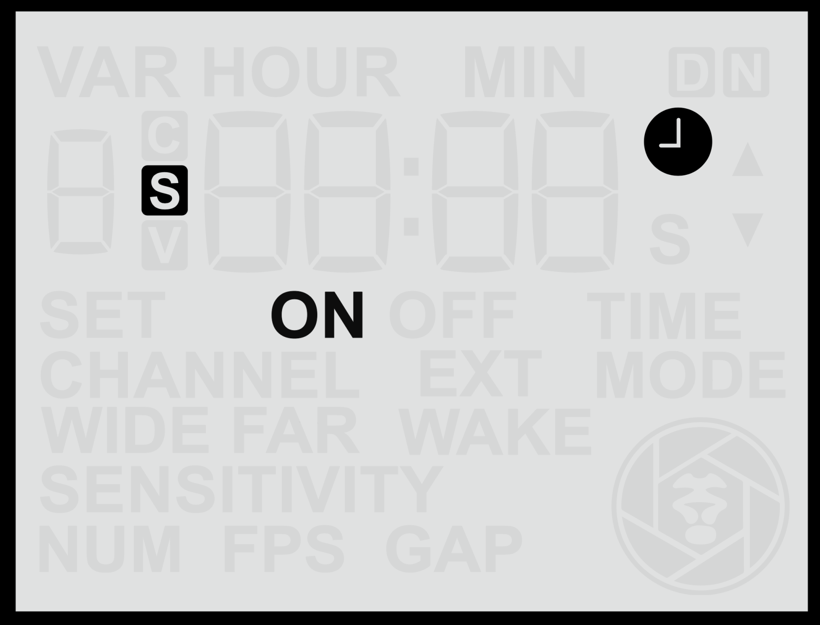
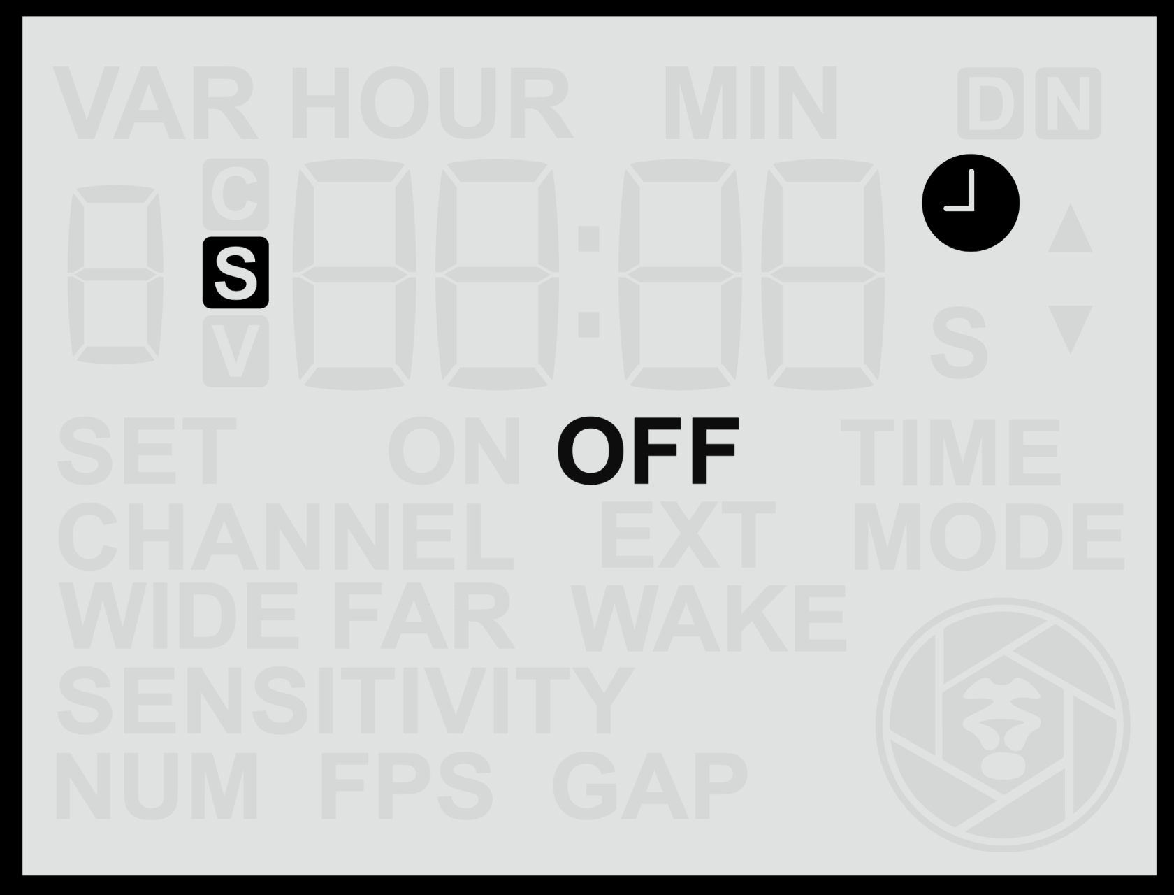
- **Clock Symbol** – Indicates that **time windows** are enabled.
The clock icon only appears when the sensor has been configured to operate during specific times of day.
- When the icon is **visible**, it means the sensor will operate during a specified time window and will be inactive outside those hours. The clock symbol will be accompanied by either **ON** or **OFF**. This provides a convenient indication of whether the sensor is currently inside an active time window (**ON**) and is therefore **working**, or outside an active time window (**OFF**) and is therefore is **disabled**.
- When the icon is **not visible**, no time window is set and the sensor will operate continuously.
|  |  |
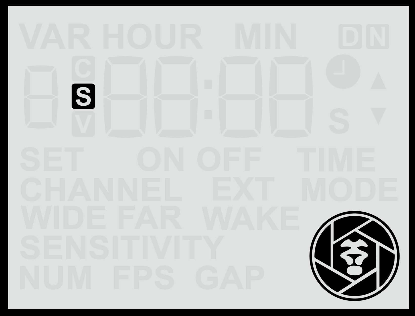
- **Camtraptions Logo (bottom-right corner)** – Acts as an **activity indicator**.
The logo appears whenever the sensor has detected motion and is executing a sequence of commands, such as triggering a camera to take photos or run a video recording.
While the logo is displayed, the sensor is “busy” and will not respond to further detections until the sequence has completed.
Once the logo disappears, the sensor has finished the current sequence and is ready to trigger again.
*Note:*
- *The sensor may appear unresponsive while the logo is displayed. This is normal behaviour — it simply means the sensor is running its programmed sequence.*
- *If a button is pressed while a sequence is running, the sequence will be cancelled and not completed.*
**
#### **Button Shortcuts from the Home Screen**
While on the Home Screen, pressing and holding certain buttons provides quick access to key information:
From the quick access screens, wait 20 seconds or press any arrow key to return to the home screen.
#### **Battery Voltage Reference**
When viewing the battery voltage, the displayed value provides an indication of the remaining battery charge. The relationship between voltage and capacity varies depending on the battery type and chemistry. For convenience, detailed [**battery voltage reference tables**](https://docs.camtraptions.com/books/pir-v4-manual/page/battery-voltage-tables "Battery Voltage Tables") are provided at the end of this manual, showing how measured voltage corresponds to approximate remaining charge for different compatible battery types.
# Front Motion Indicator Light
The **Front Motion Indicator Light** is a useful tool for **testing the sensor’s field of view and detection range** during setup. When active, the light flashes **red** through the white PIR lens whenever motion is detected, helping you visualise exactly when and where the sensor is responding.
The indicator light remains active for **five minutes** after the sensor is first powered on or after any button is pressed. It then automatically **disables** to conserve power and to prevent the light from drawing attention to the sensor while it is deployed in the field.
The light is **bright and visible** in a wide range of lighting conditions, making it effective for setup in both indoor and outdoor environments.
For practical guidance on using the indicator light to refine the trigger area, see the [**Controlling the Field of View**](https://docs.camtraptions.com/books/pir-v4-manual/page/controlling-the-field-of-view "Controlling the Field of View") section of this manual.
# Navigating the Menu
The Camtraptions PIR Sensor v4 features a simple and intuitive **menu system** that allows you to adjust all key settings directly from the built-in screen and keypad.
When the menu is inactive, the screen will revert to the **Home Screen**. To access the menu, press the **Left** or **Right** buttons to cycle through the available screens. The list of menu screens will differ depending on whether the sensor is set to **Still Photo Mode** or **Video Mode**.
#### **Adjusting a Setting**
1. Navigate to the desired menu screen using the **Left** or **Right** buttons.
2. Press the **Up** or **Down** button — the setting’s value will begin to **flash**.
3. Use the **Up** or **Down** buttons to adjust the value to your preference.
4. Press the **Set** (centre) button to **save** the change.
If you move to another screen while a value is still flashing (without pressing **Set**), the change will **not** be saved.
When you reach the end of the available screens, the menu will loop back to the **Home Screen** automatically.
#### **Additional (Hold) Functions**
Some menu screens have **secondary functions** that can be accessed by **holding** the **Up** or **Down** buttons. For example:
- **Sensor configuration screens (Far / Wide):**
Holding the **Up** button cycles the sensor mode between **Enabled**, **Disabled**, and **Wake-Only**.
- **Wireless Channel screen:**
Holding the **Down** button **disables** the wireless transmitter completely, switching the sensor to wired-only operation.
Refer to the individual **Settings** sections later in this manual for detailed descriptions of each menu screen and the available configuration options.
# Setting the Operating Mode (Stills or Video)
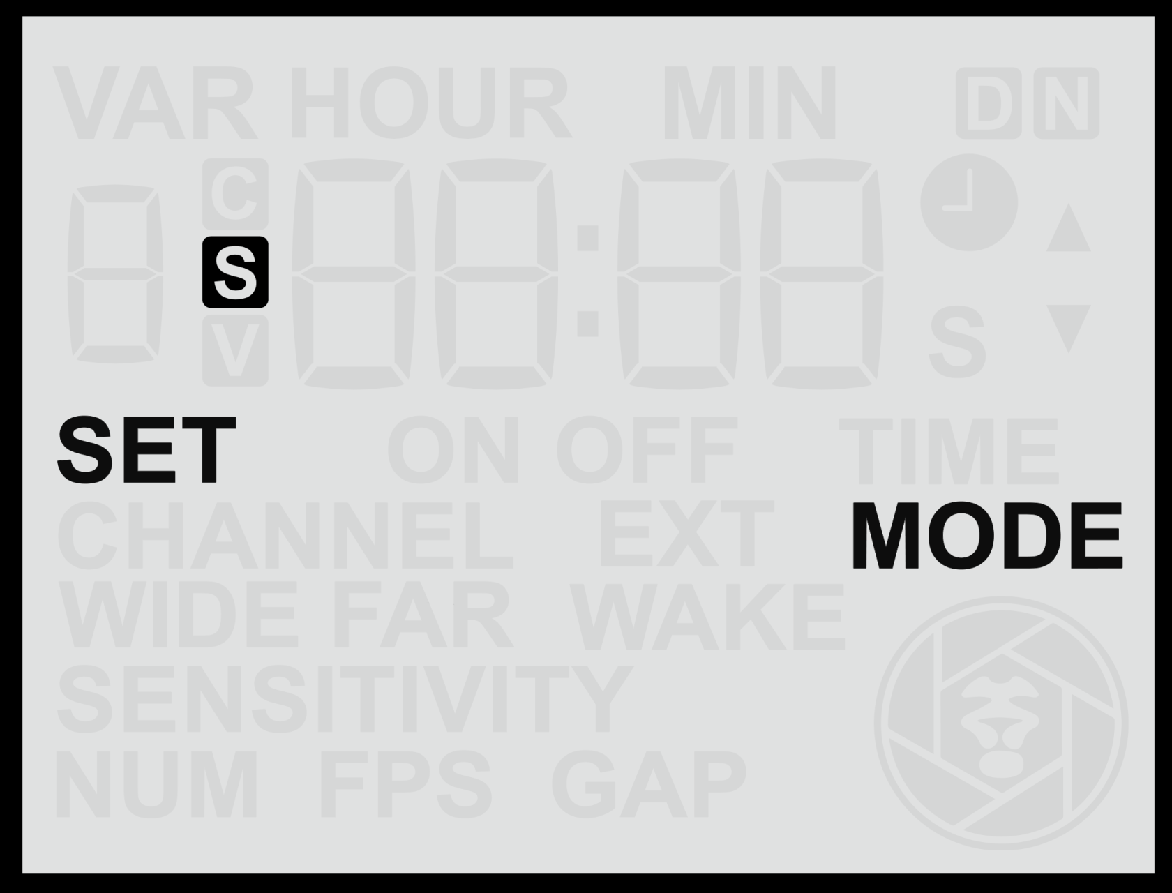
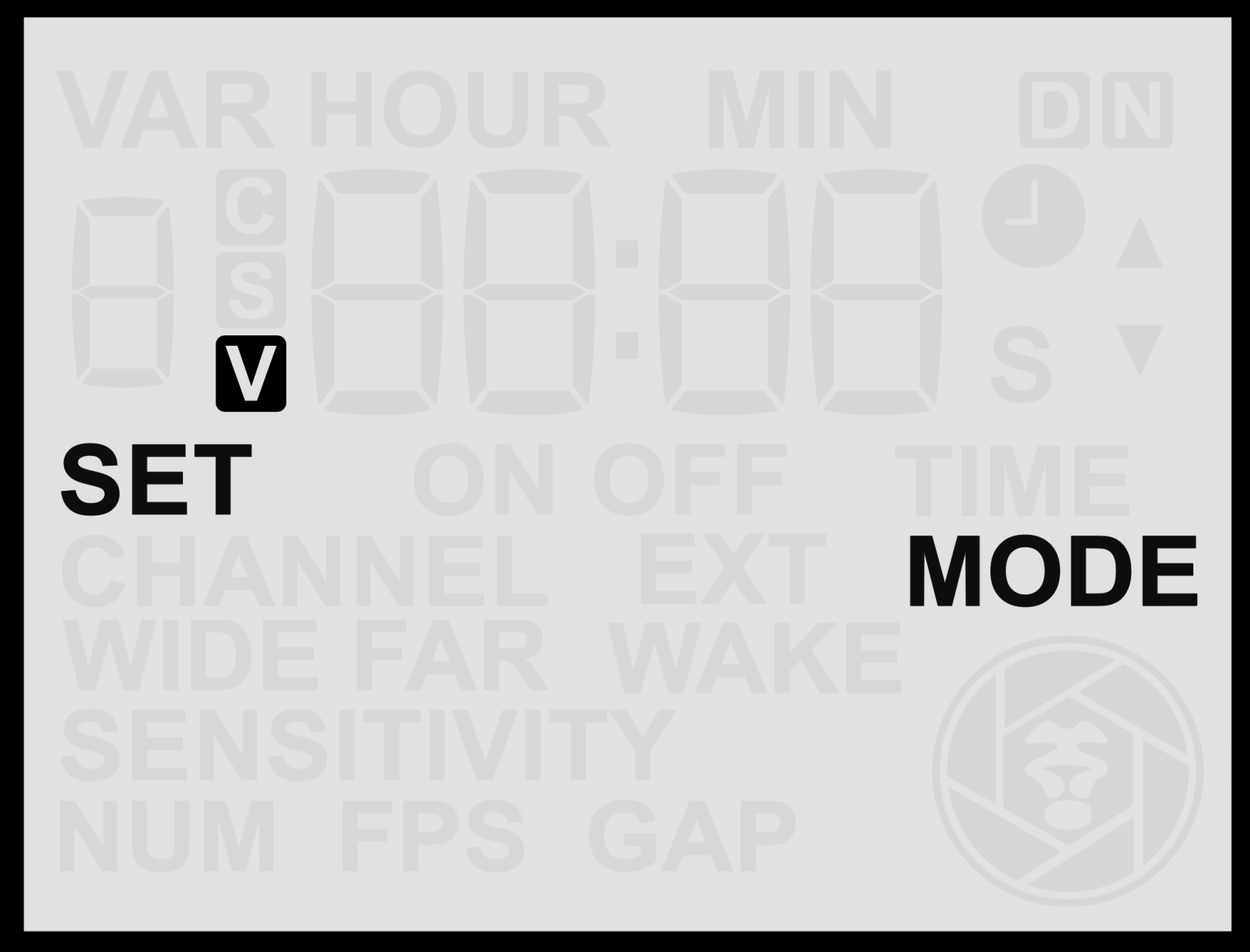
The **Set Mode** screen allows you to choose whether the sensor operates in **Still Mode** or **Video Mode**. This determines which set of menu screens and settings will be available.
|  |  |
#### **Changing the Operating Mode**
1. From the **Home Screen**, press the **Left Arrow** once to reach the **Set Mode** screen.
2. Use the **Up** or **Down** buttons to toggle between:
- **S** — *Still Mode*
- **V** — *Video Mode*
#### **Notes**
- The **current mode** is always shown on the **Home Screen** as either **S** (Still) or **V** (Video).
- Changing mode will update the available menu screens to show the relevant settings for that mode.