Parts List
This section identifies the components supplied with the Quick Deploy Camera Trap. Some parts are common to both configurations, while others are specific to either the Wireless or Wired system. Check that all listed items are present before beginning assembly.
Common Components
1. Quick Deploy Frame Parts Box
A box containing:
| Image | Part Name | Quantity | Purpose |
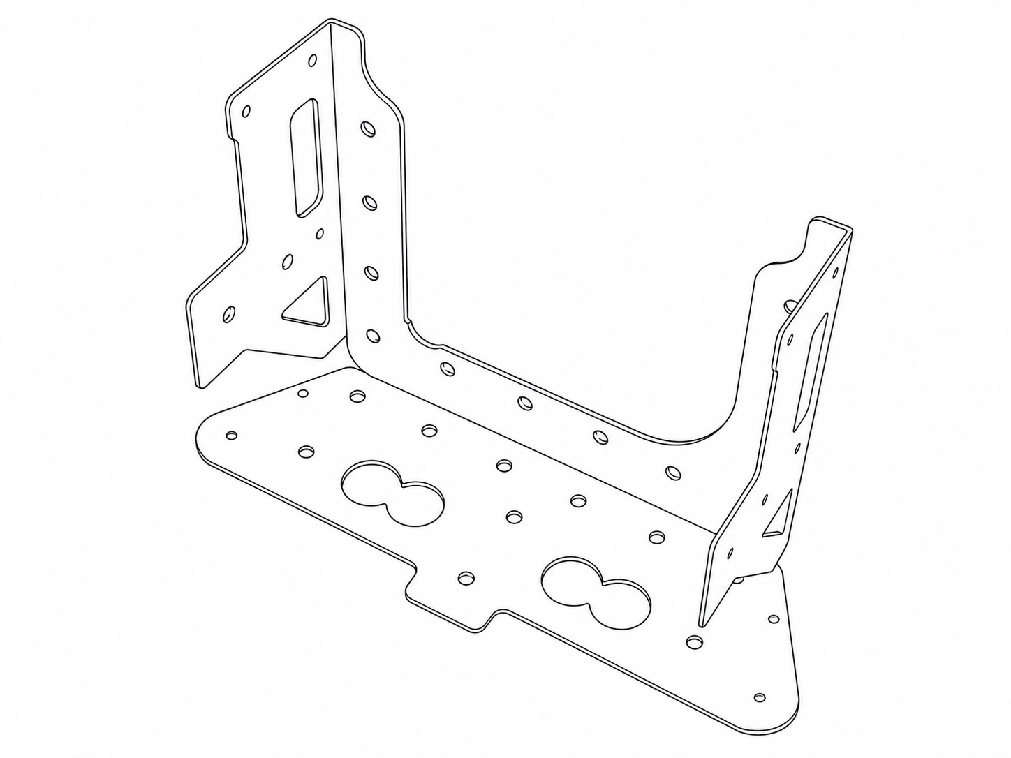 |
Frame Base | 1 | The primary central part of the Quick Deploy Frame. Two screws secure it to the bottom of the camera housing. |
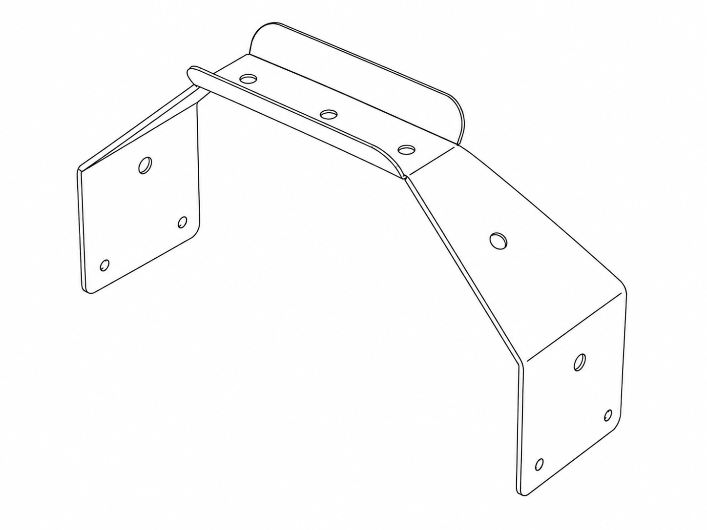 |
Frame Handle | 1 | Quick Deploy Frame Handle. |
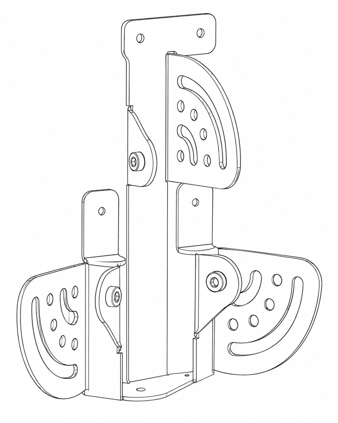 |
Left Bracket | 1 | Attaches to the left side of the Frame Base when looking towards the front face of the frame. Provides pivoting attachment point for legs and arms. |
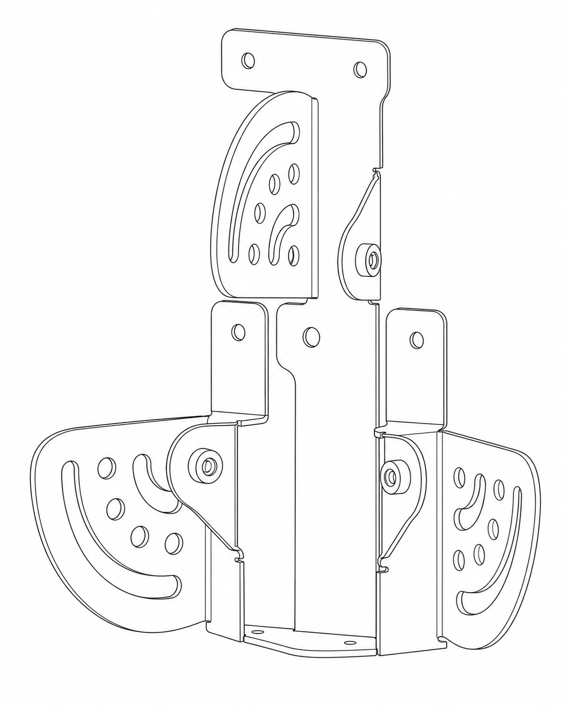 |
Right Bracket | 1 | Attaches to the right side of the Frame Base when looking towards the front face of the frame. Provides pivoting attachment point for legs and arms. Two screws secure it to the side of the camera housing. |
2. Quick Deploy Tubes Pack
A pack containing:
| Image | Part Name | Quantity | Purpose |
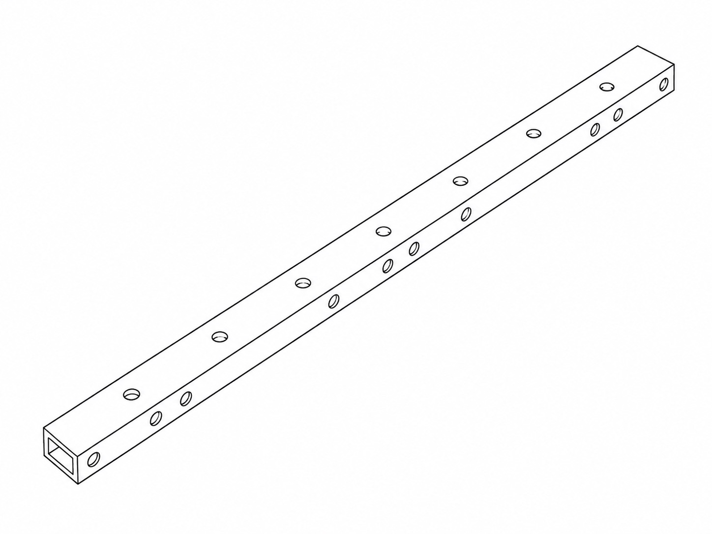 |
300mm Tube | 4 | Four legs. |
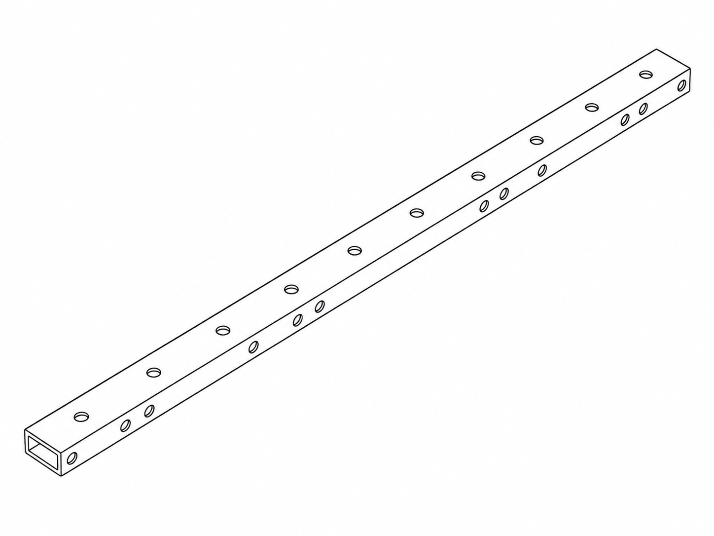 |
400mm Tube | 2 | Two pivoting arms for the flashes. |
3. Quick Deploy Fasteners Pack
A bag containing:
| Image | Part Name | Quantity | Purpose |
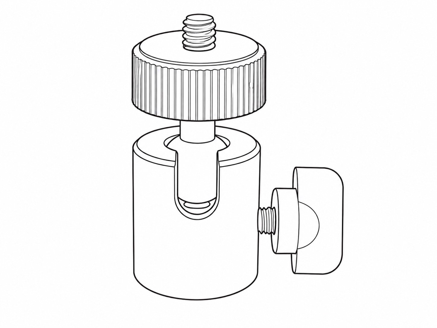 |
Mini Ball Head | 3 | For mounting the two flash housings and the PIR sensor. |
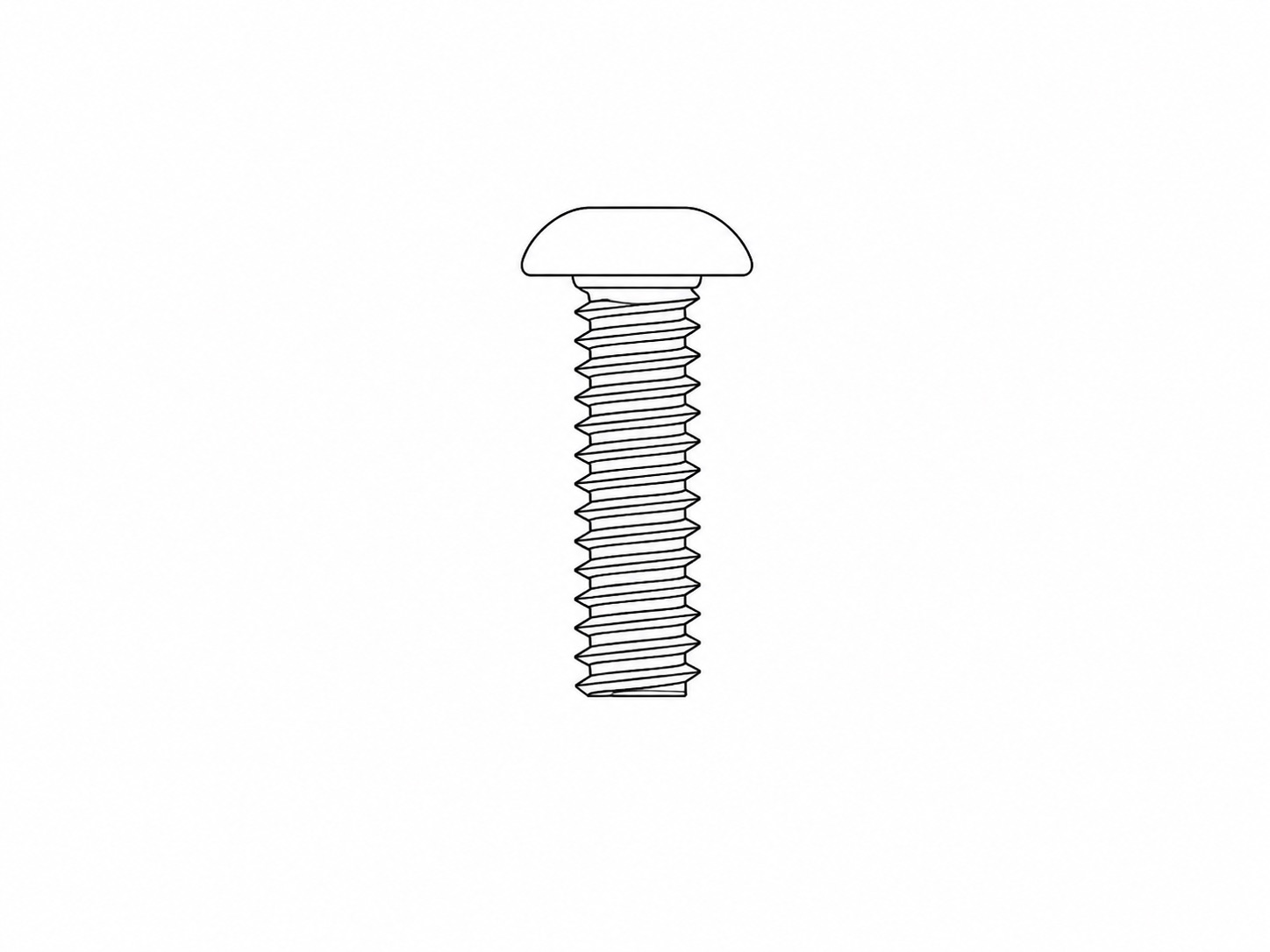 |
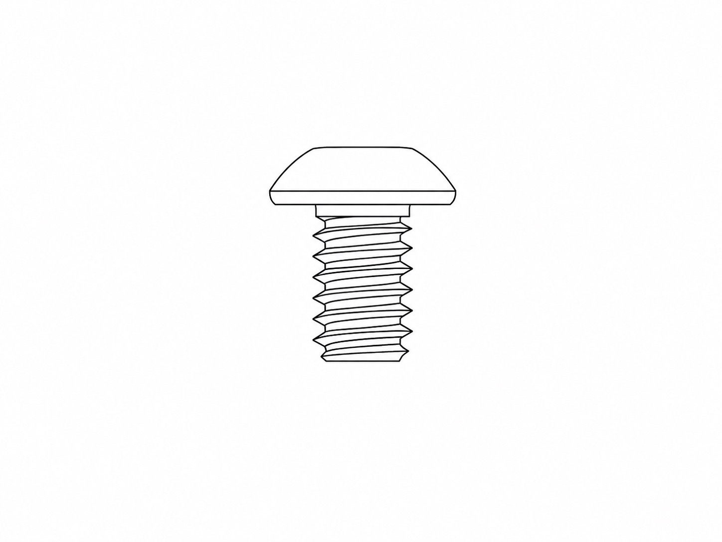
3/4 Inch Button Head Screw
|
3 | Two of these are for mounting the Mini Ball Heads for the flashes. One extra is supplied for optionally mounting the PIR's Mini Ball Head on a leg or arm. |
 |
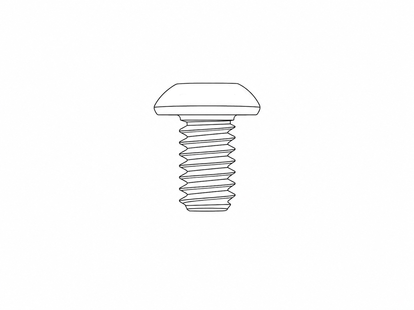
5/16 Inch Button Head Screw
|
3 | The shortest button head screw in the pack. One for mounting the PIR's Mini Ball Head on the Frame Handle. Two for securing the bottom of the Camera Housing to the Frame Base. |
 |
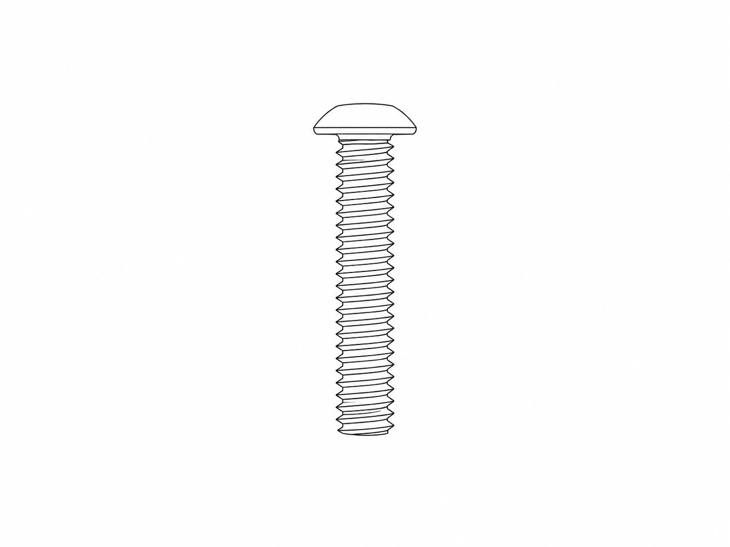
3/8 Inch Button Head Screw
|
2 | For securing the side of the Camera Housing to the Frame Base and Right Bracket. |
 |
1.25 Inch Button Head Screw
|
6 | Attaches each arm and leg to the left and right brackets. The legs and arms pivot on these screws. |
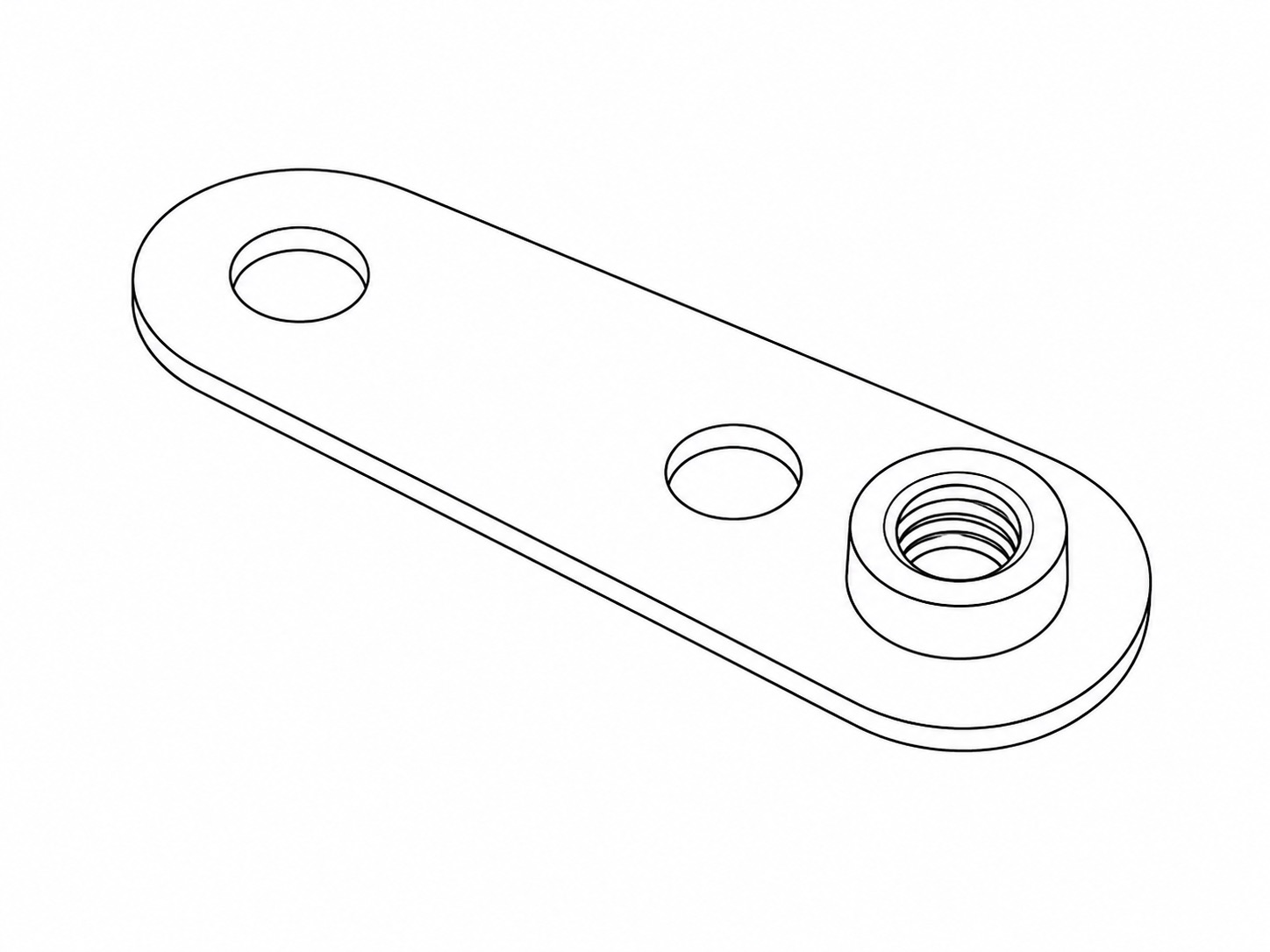 |
Friction Plate
|
6 | Part of the pivoting assembly for each arm and leg. Each 1.25 Inch Thumbscrew fastens into the thread on these Friction Plates to secure the arms and legs. |
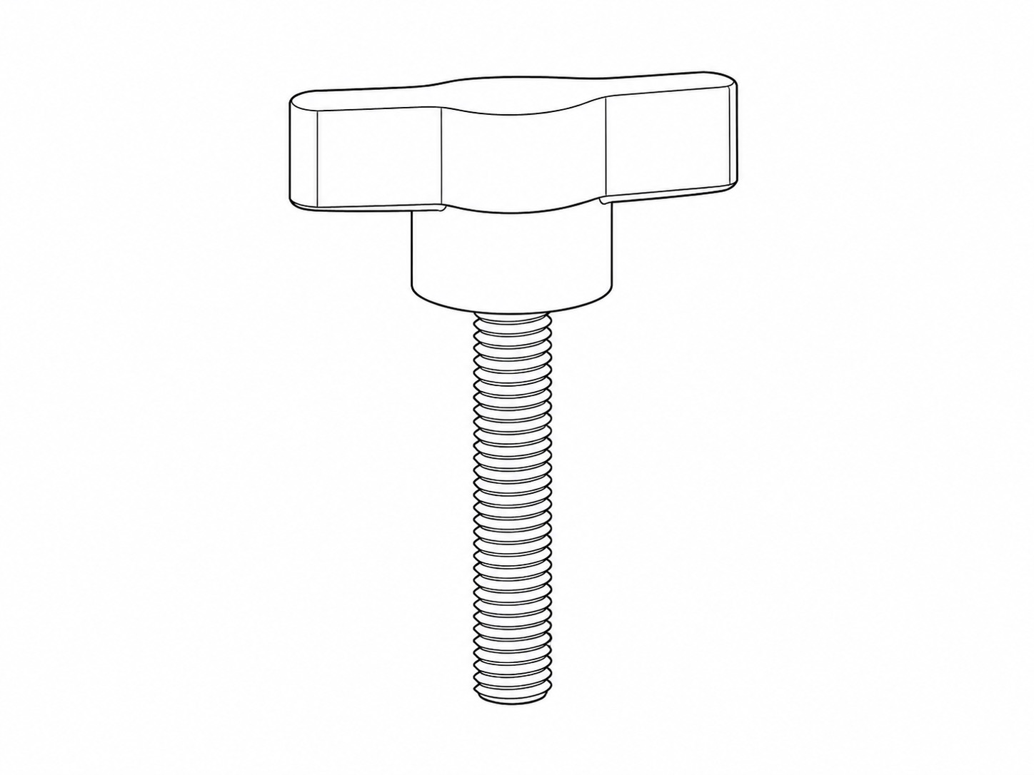 |
1.25 Inch Thumbscrew
|
6 | The primary adjustment and clamping screw for each arm and leg. |
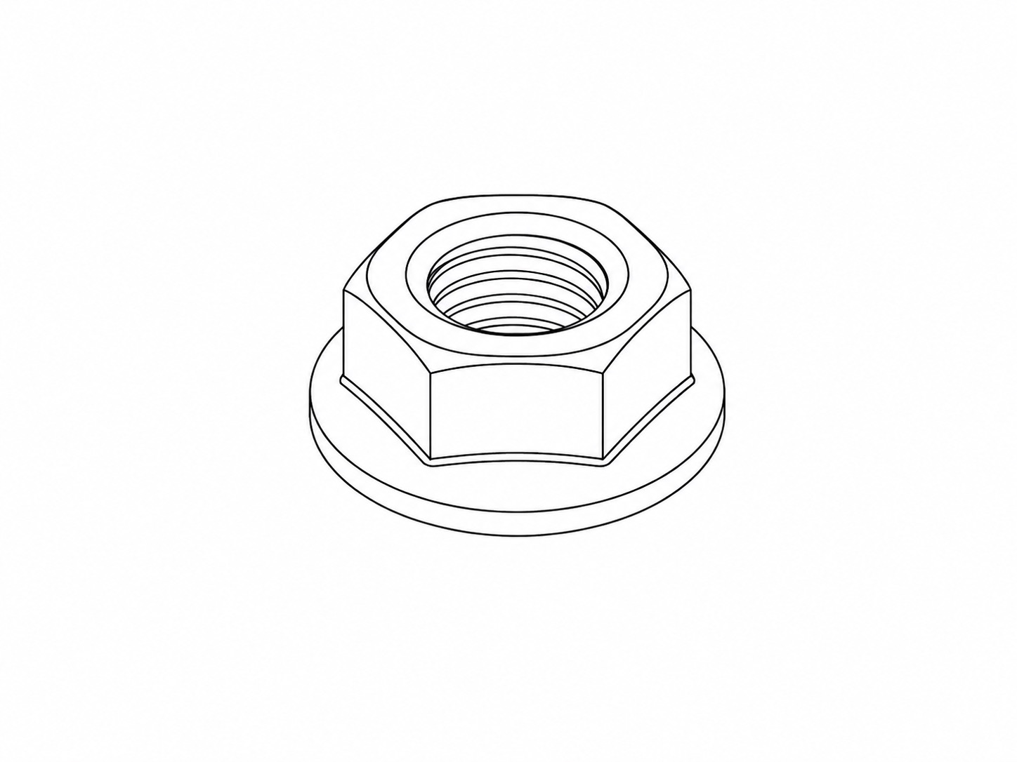 |
Serrated Nut
|
6 | Optional nuts for allowing the Thumbscrews to fasten through the pre-defined holes in the Left and Right Brackets + Friction Plates, in order to create a more locked/anti-slip assembly. |
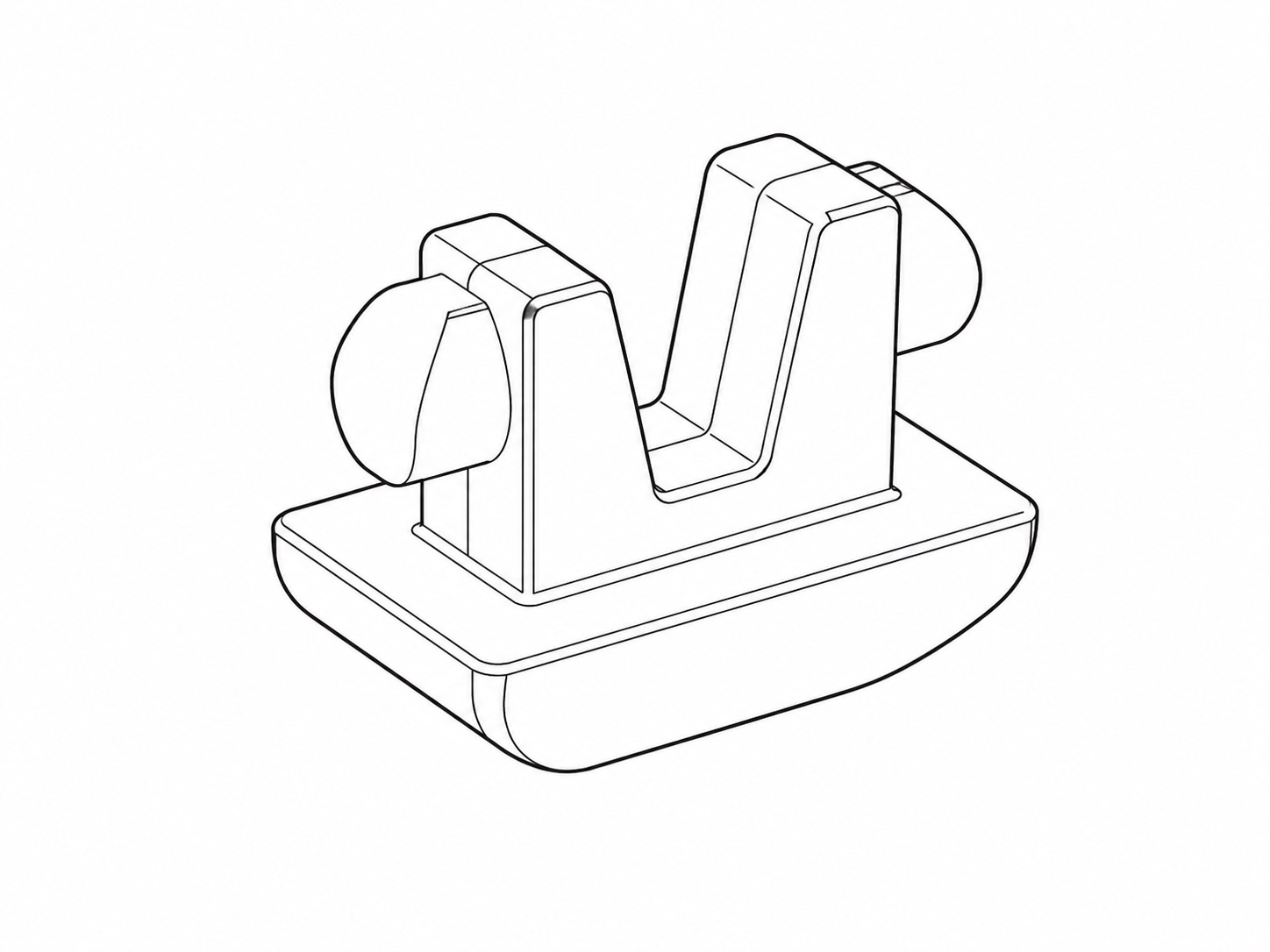 |
Rubber Foot
|
4 | A rubberised foot for the bottom of each leg. |
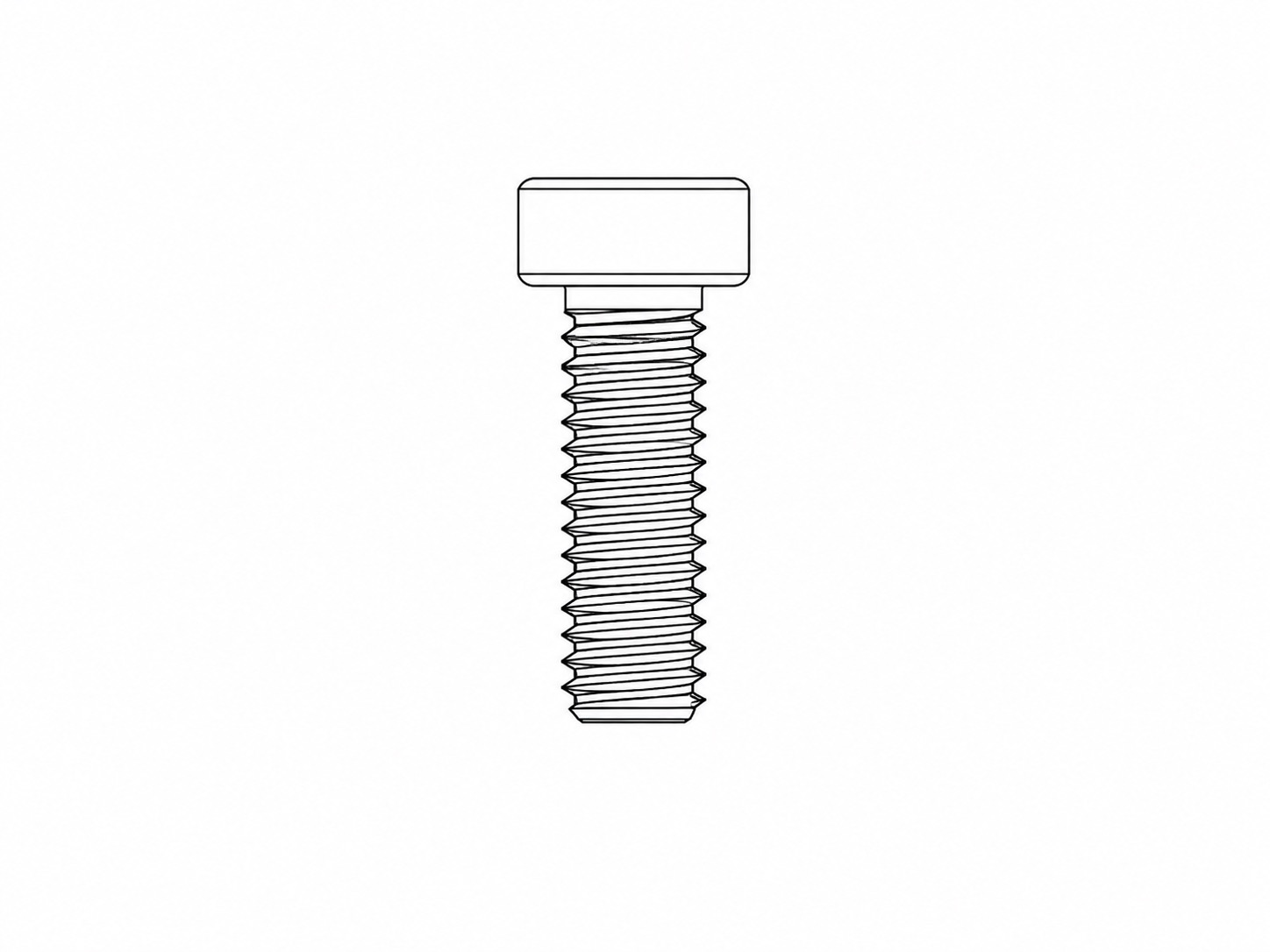 |
M4 10mm Cap Head Screw
|
12 | For fastening the Left Bracket and Right Bracket to the Frame Base and Frame Handle. |
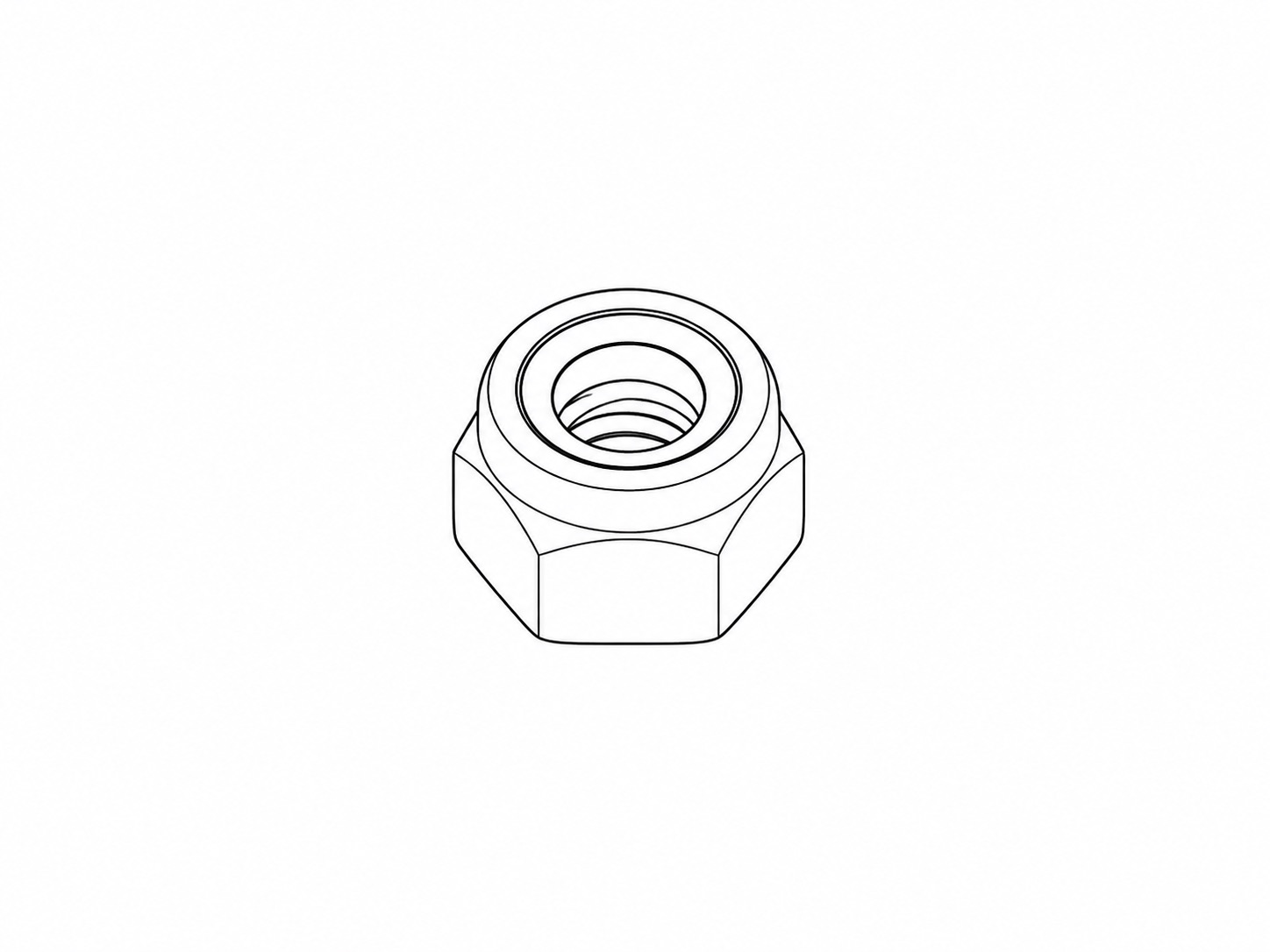 |
M4 Nut
|
12 | For fastening the Left Bracket and Right Bracket to the Frame Base and Frame Handle. |
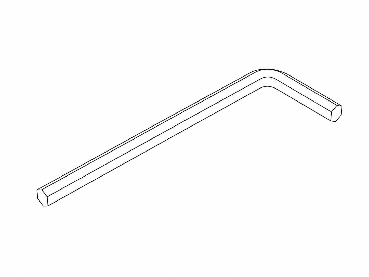 |
4mm Hex Key
|
1 | For initial assembly of the Quick Deploy Frame (fastening all of the Button Screws). |
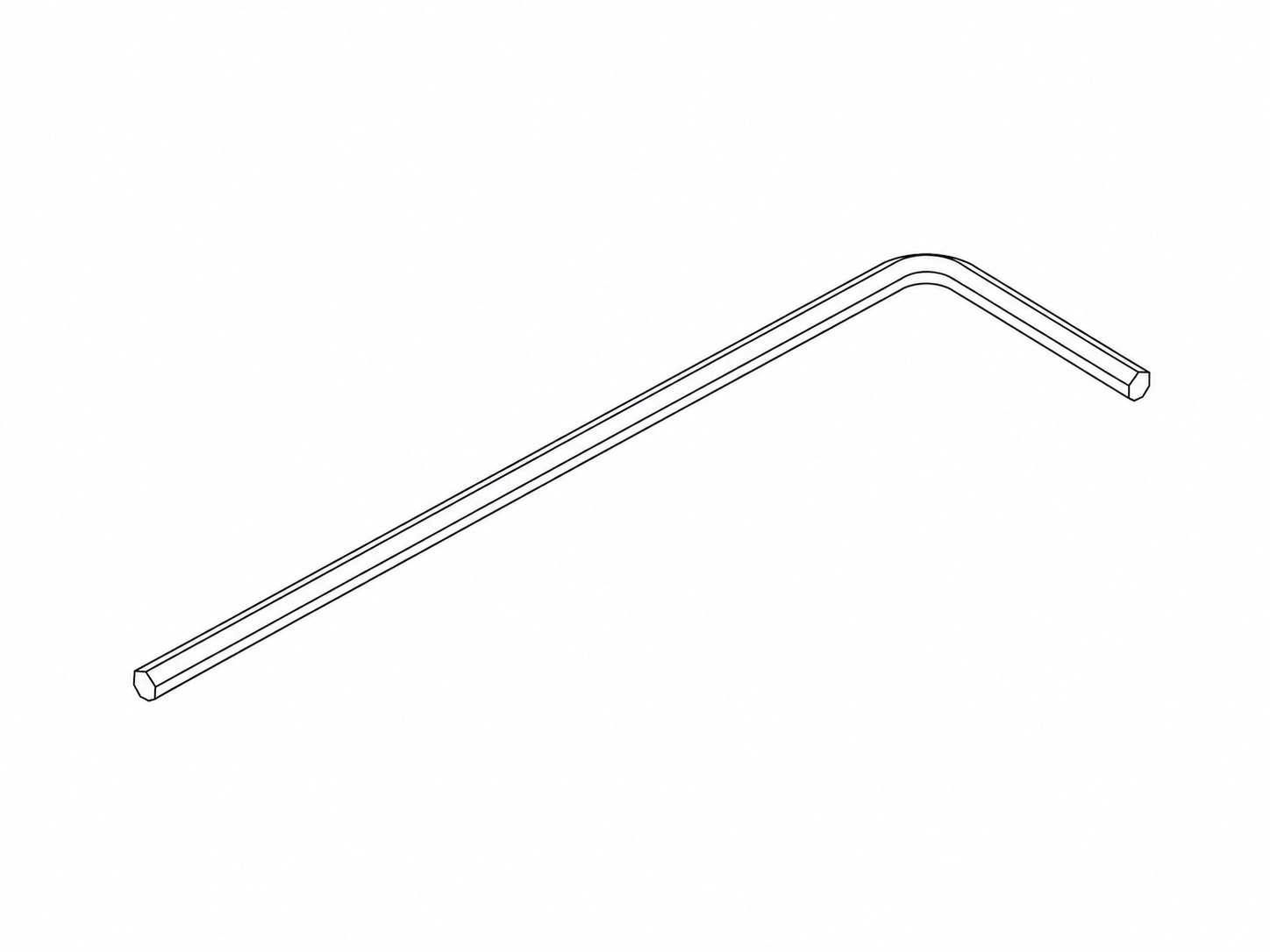 |
2.5mm Hex Key
|
1 | For initial assembly of the Quick Deploy Frame (fastening the M4 screws and nuts). |
4. Other Equipment
| Image |
Part Name |
Quantity |
Purpose |
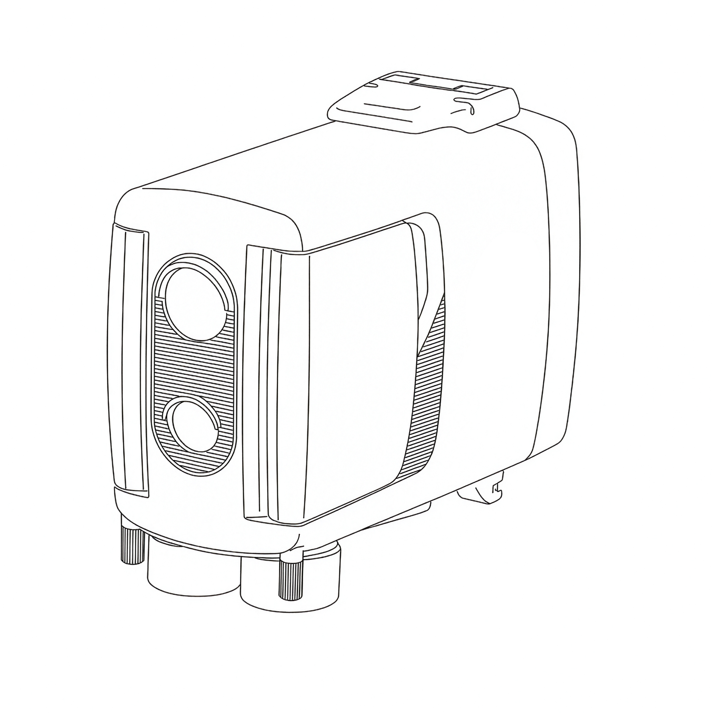 |
PIR Motion Sensor v4 | 1 | Detects motion and triggers the camera to take a photo. |
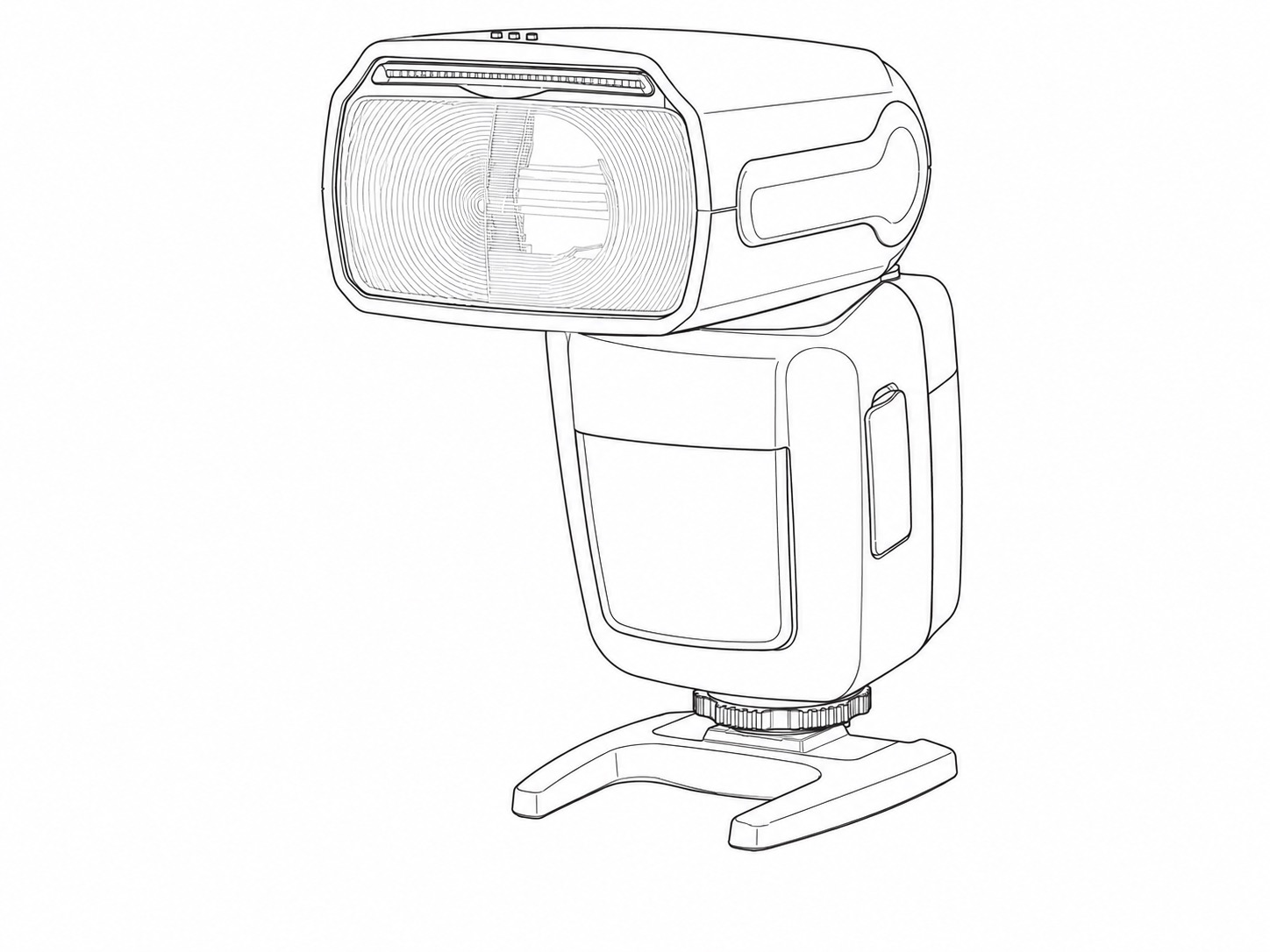 |
Z Pro Camera Trap Flash | 2 | Provides illumination in darker conditions and during the night. |
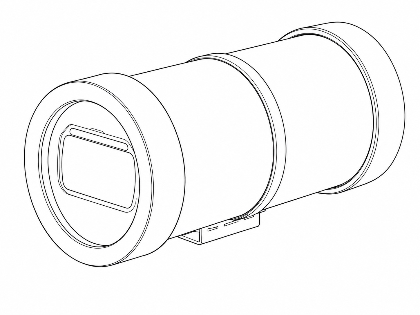 |
Flash Housing | 2 | Provides physical and weather protection for the Z Pro Flashes. |
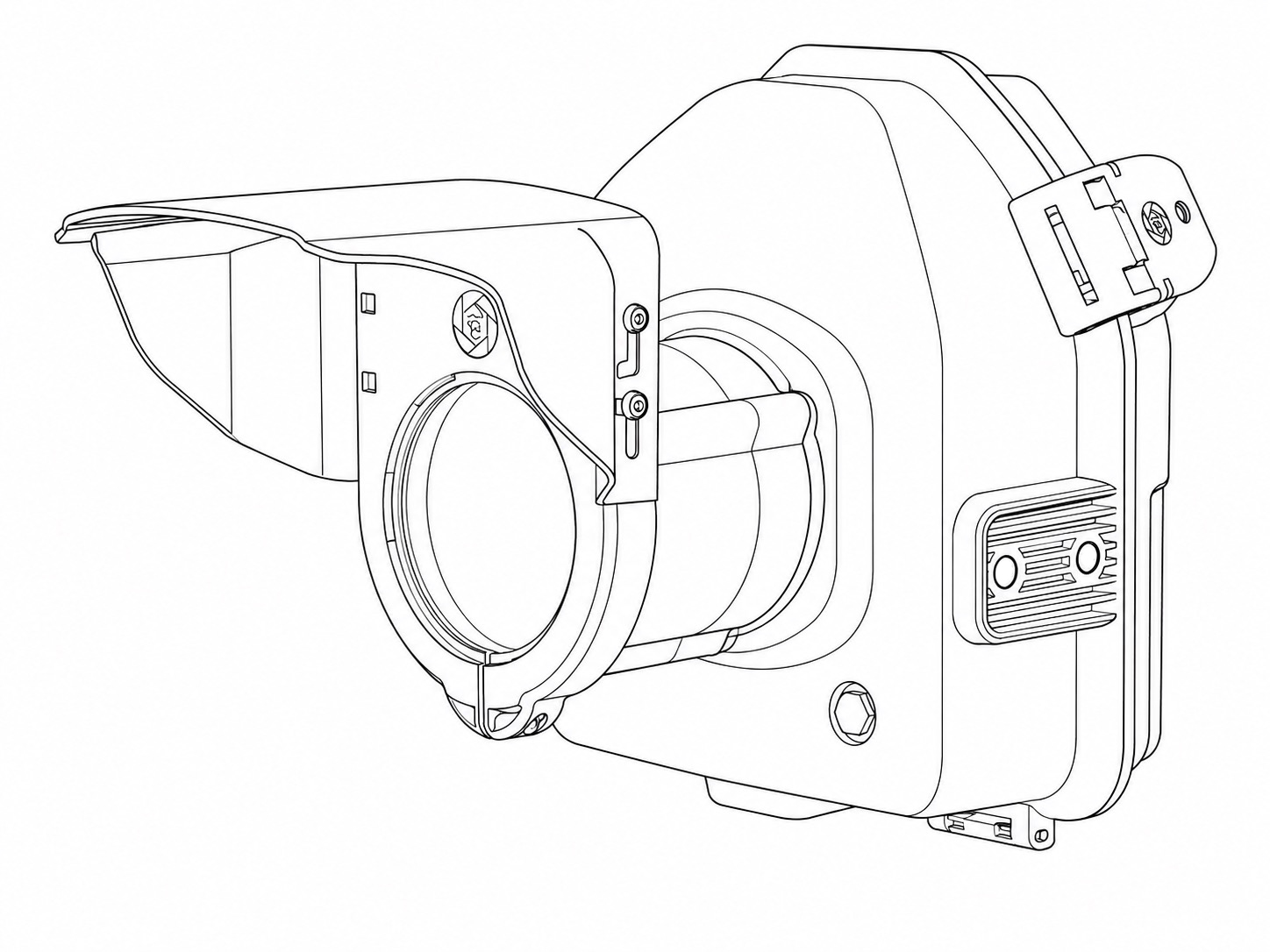 |
Camera Housing | 1 | Provides physical and weather protection for the camera. |
 |
Camera Housing Glass Window | 1 | Part of the assembled Camera Housing. |
Wireless-only Components
1. Wireless Trigger Equipment
| Image |
Part Name |
Quantity |
Purpose |
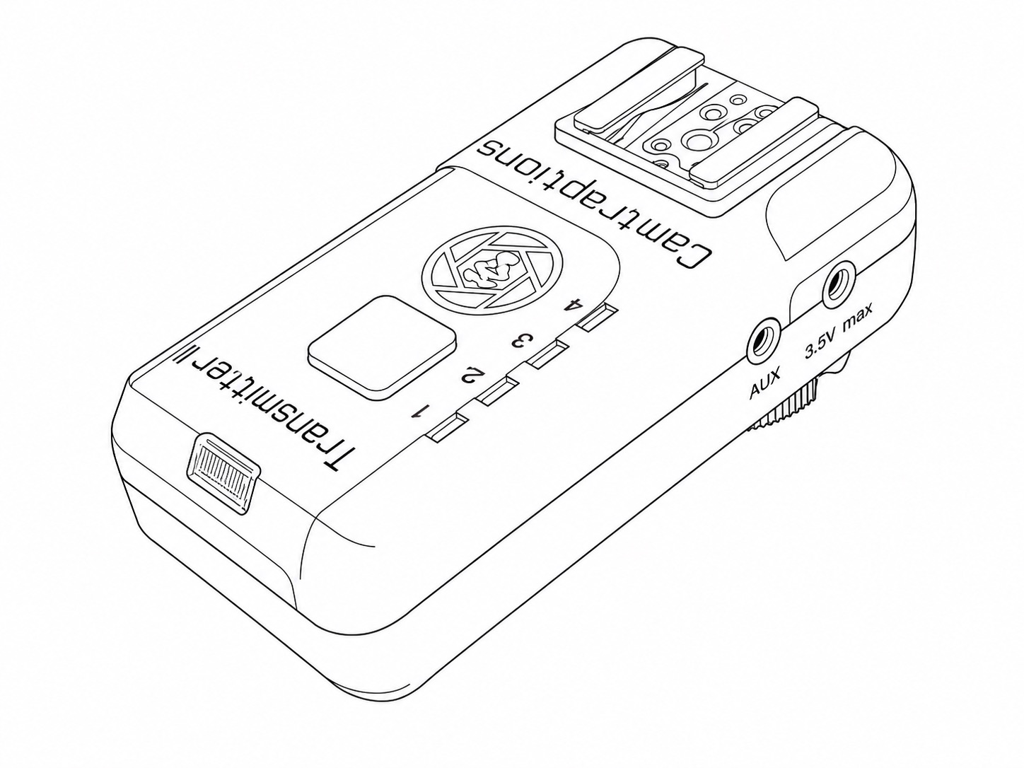 |
Wireless Transmitter v2 | 1 | Mounted directly in the camera's flash hot shoe. Sends wireless flash trigger signals to the two Receivers mounted on the two Z Pro Flashes. |
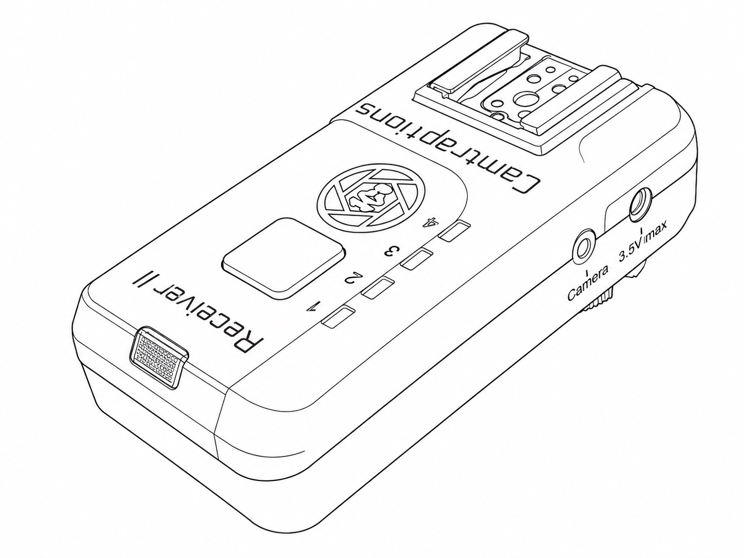 |
Wireless Receiver v2 | 3 | One Receiver is loose inside the Camera Housing and connected to the camera's shutter release socket via a Camera Connecting Cable (sold separately). Each of the other two Receivers is mounted on a Z Pro Flash. |
 |
|
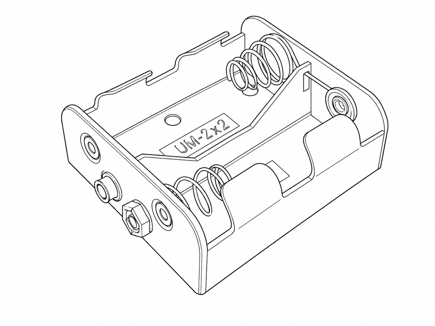
3 | Can be optionally plugged into the wireless triggers to power them using C size cells for around two months of life. |
 |
|
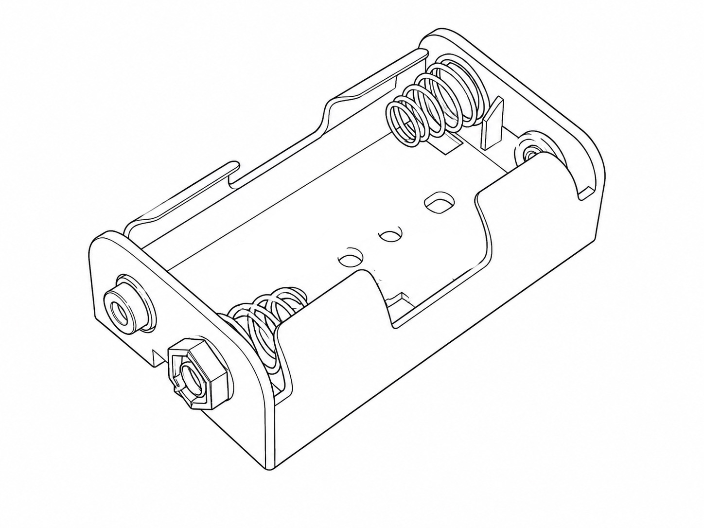
3 | Can be optionally plugged into the wireless triggers to power them using AA size cells for around two weeks of life. |
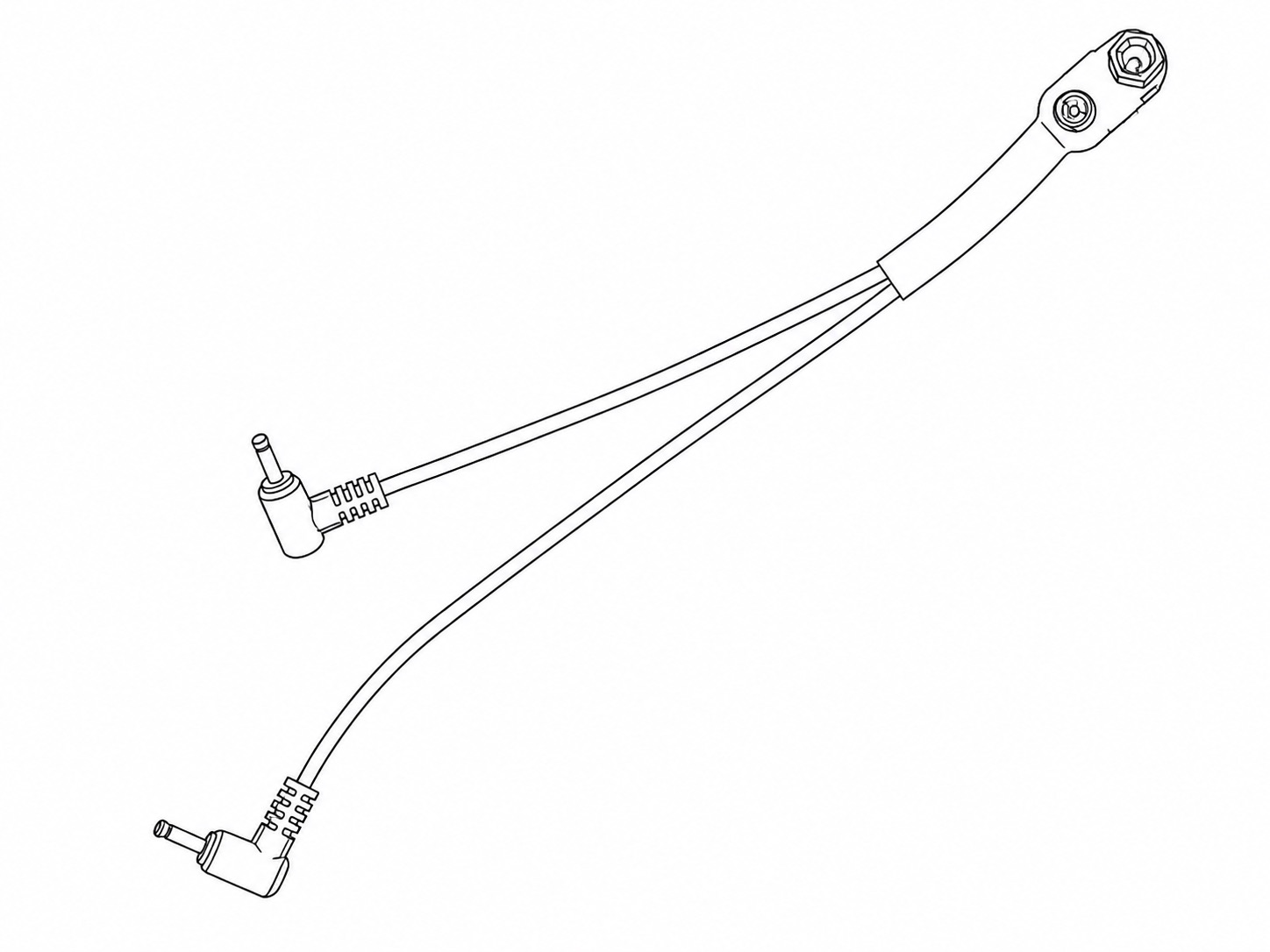 |
|
1 | Connects one 2xC or 2xAA Battery Holder to the Transmitter and Receiver contained inside the Camera Housing. |
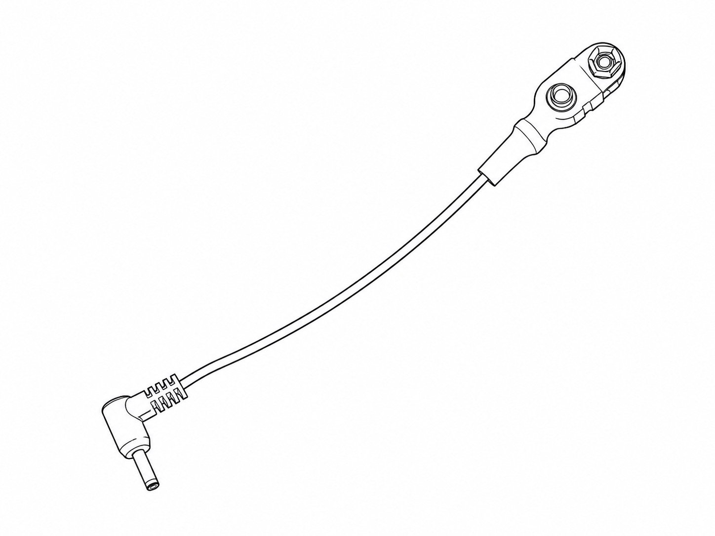 |
|
2 | Connects one 2xC or 2xAA Battery Holder to the Receivers mounted on each Z Pro Flash. |
Wired-only Components
1. Quick Deploy Cables Pack
A bag containing:
| Image |
Part Name | Quantity |
Purpose |
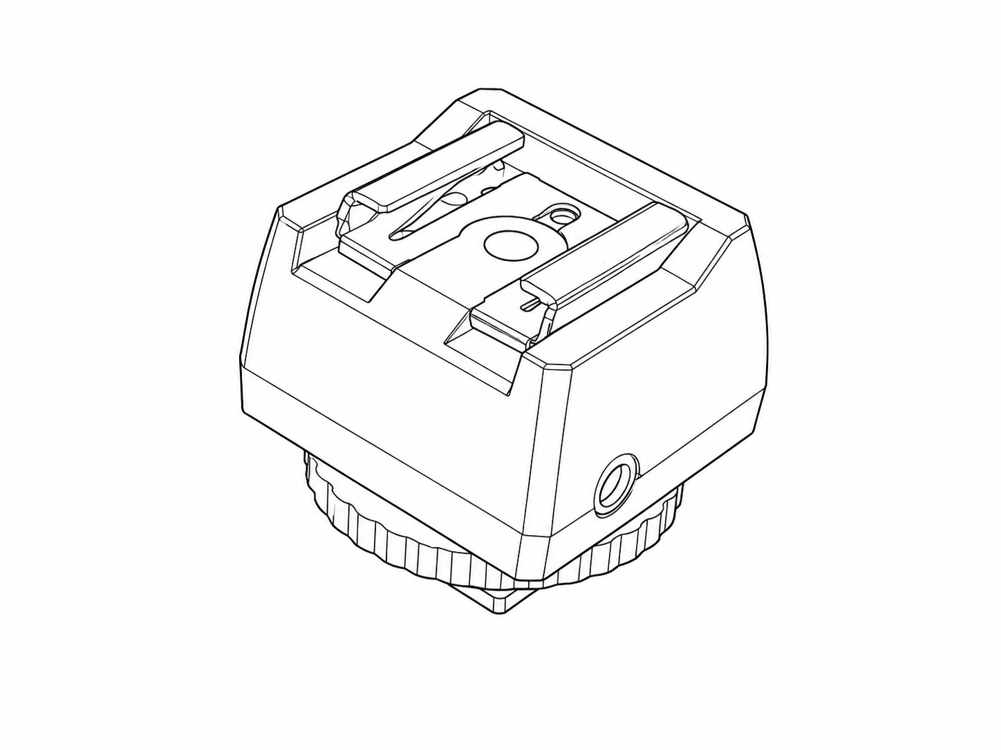 |
Flash Hot Shoe Adapter
|
1 | Mounted directly in the camera's flash hot shoe. Transfers the camera's "flash shoot" signals into the cable system. |
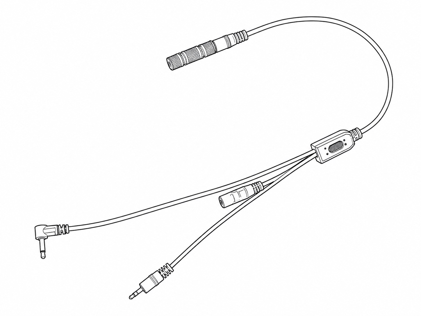 |
Wired Z Pro Flash Adapter
|
1 | Important for ensuring that the Z Pro Flashes are woken up from sleep and triggered reliably. |
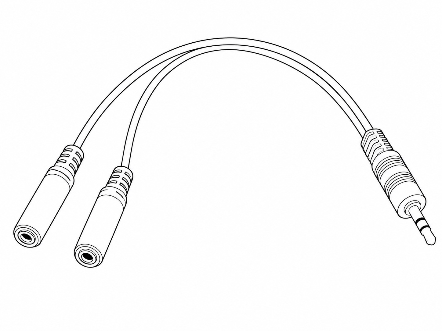 |
2 Way Flash Splitter
|
1 | Connects from the Wired Z Pro Flash Adapter to the two Waterproof Flash Signal Cables. |
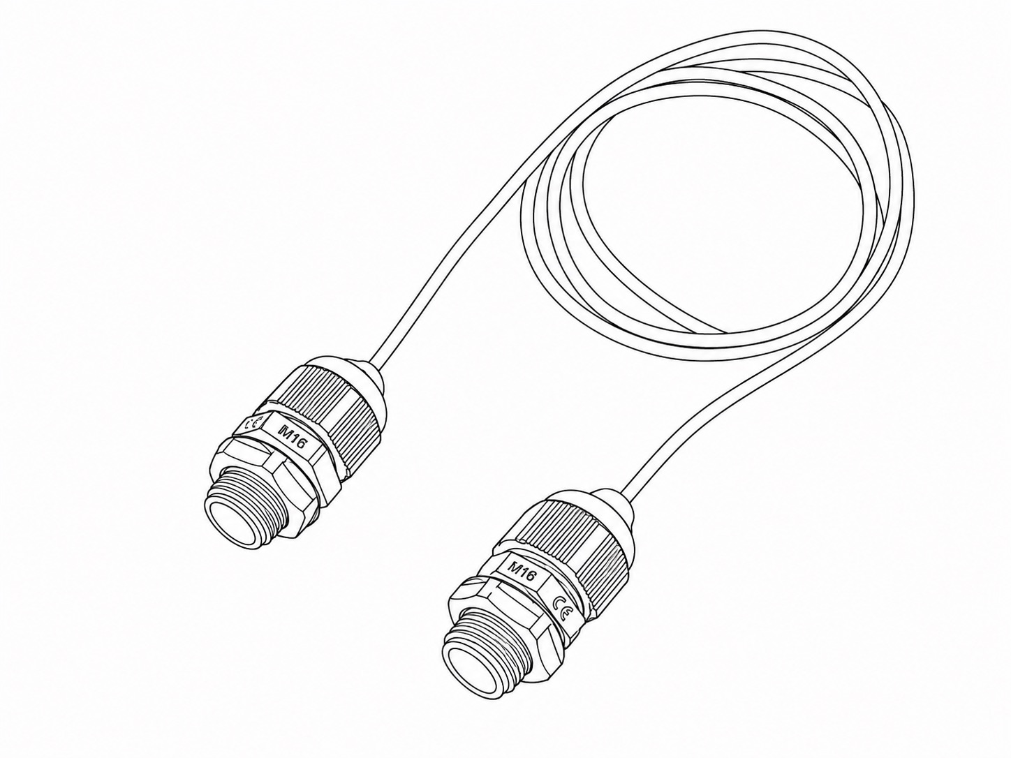 |
Waterproof Flash Signal Cable | 2 | Transfers the flash signals from the Camera Housing to the two Flash Housings. |
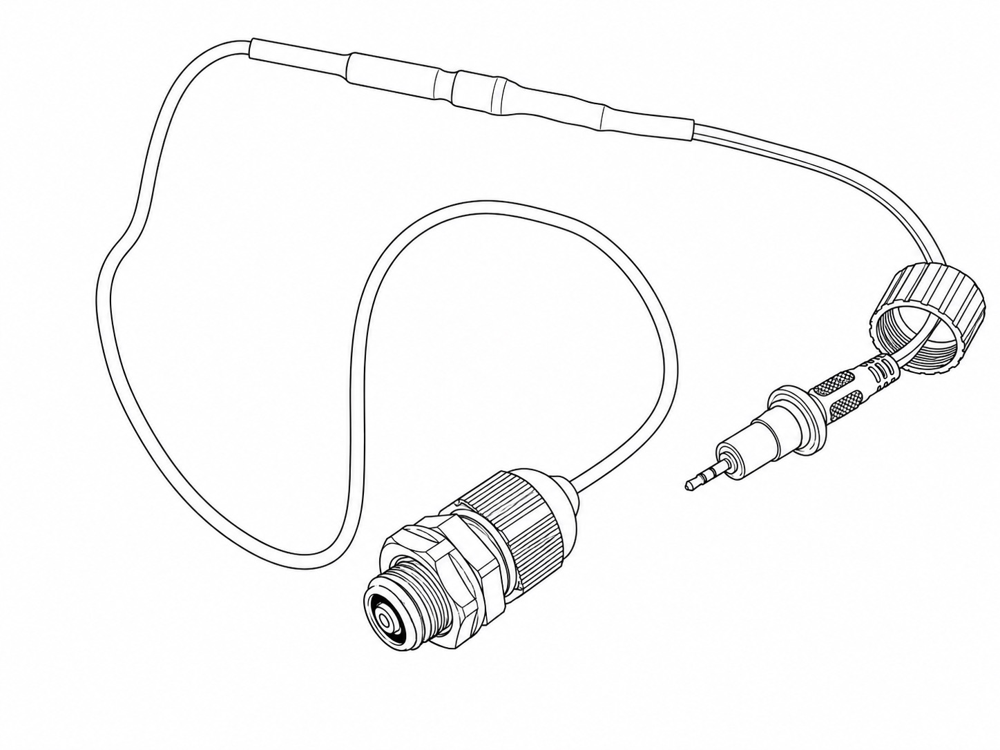 |
Waterproof PIR Signal Cable | 1 | Transfers the PIR Sensor's trigger signals to the Camera Housing. |
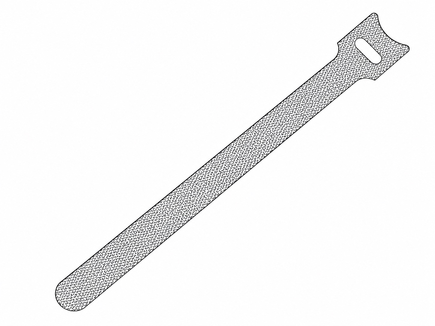 |
Hook-and-loop Cable Tie | 5 | Provided to keep the cabling neat and secure. |
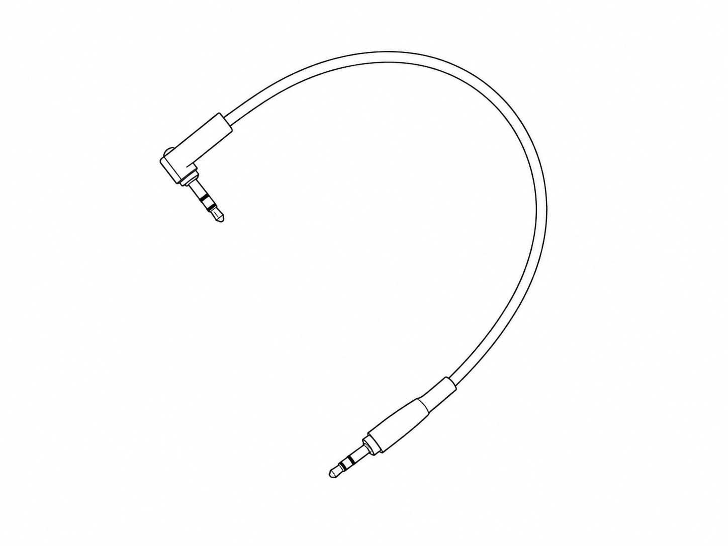 |
20cm Flash Cable | 2 | Contained within each Flash Housing. Connects from the Waterproof Flash Signal Cable to the sync socket on the side of each Z Pro Flash. |