Quick Deploy Camera Trap Manual
Introduction
The Introduction provides an overview of the Camtraptions Quick Deploy Camera Trap — explaining the purpose of the system, the differences between the Wireless and Wired configurations and providing important safety notices.
This manual covers the Quick Deploy Camera Trap system as a whole, including its components, configurations and assembly. It is intended to be read alongside the individual product manuals for the Camtraptions PIR Motion Sensor v4, Weatherproof Camera Housing, Weatherproof Flash Housings, Z Pro Flashes and, for the Wireless version, Camtraptions Wireless Triggers. Refer to these individual manuals for detailed information on operating, configuring, powering and maintaining each product.
System Overview
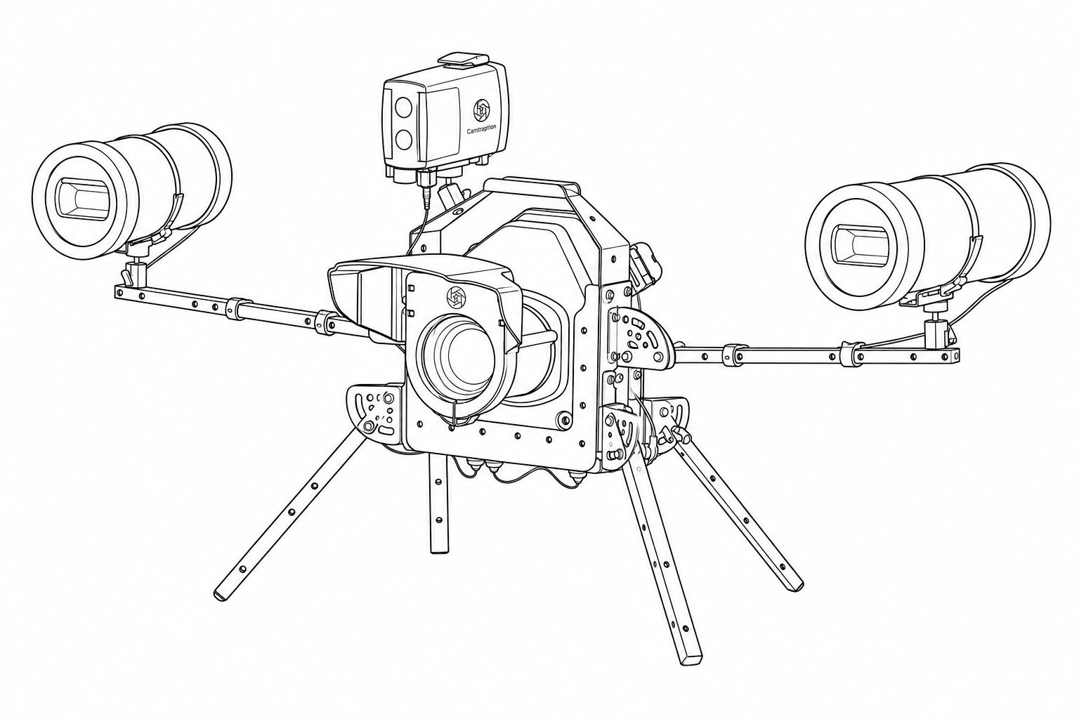
The Camtraptions Quick Deploy Camera Trap is a complete, portable camera-trap system for creating high-quality wildlife photographs with a DSLR or mirrorless camera and two off-camera flashes.
It is designed to make camera trapping quicker and more practical in the field. The camera, PIR Motion Sensor and flashes are mounted on a single adjustable frame, allowing the complete setup to be carried into position, refined and redeployed without dismantling the system. This makes it well suited to temporary or long-term setups at locations such as trails, burrows, waterholes and other animal activity points.
At the centre of the system is the Quick Deploy Frame, which supports a weatherproof camera housing, two flashes inside weatherproof housings and a PIR Motion Sensor. Folding legs, adjustable flash arms and compact ball heads allow the camera, sensor and flashes to be positioned independently and securely. All routine adjustments can be made without tools.
When the PIR Motion Sensor detects movement, it triggers the camera and both flashes together. During periods of inactivity, the system remains in a low-power standby state to help maximise battery life. The camera and flashes are designed to wake and fire simultaneously, providing full flash illumination from the first image in a sequence.
Wireless and Wired Configurations
The Quick Deploy Camera Trap is available in Wireless and Wired versions. Both use the same core frame, camera housing, PIR Motion Sensor and dual-flash arrangement. The Wired version uses waterproof signal cables between the sensor, camera and flashes, while the Wireless version uses Camtraptions wireless triggers, allowing the sensor and flashes to be positioned separately from the camera where required.
Safety Notices
The Quick Deploy Camera Trap contains multiple components mounted on an adjustable frame. Take care when carrying, positioning and adjusting the system, particularly when a camera, flashes and batteries are fitted due to the additional weight.
Always support the part of the system you are adjusting before, during and after releasing any thumbscrew, nut or other fastening. Keep fingers clear of moving joints, folding legs and other potential pinch points.
Make adjustments slowly and carefully to avoid injury or damage to the equipment. Adjust one part of the frame at a time. Do not loosen multiple thumbscrews or fastenings simultaneously, as this may allow part of the system to move unexpectedly.
Before leaving the system unattended, check that all clamps, thumbscrews, mounts and legs are securely tightened, and that the Camera Housing, PIR Motion Sensor and Flash Housings are properly supported. Position the system on stable ground or secure it appropriately to prevent it from falling or being dislodged.
Take particular care when working on uneven ground, in wet conditions or at height. Do not place the system where it could create a hazard to people, animals or property.
Use only compatible batteries, cables and accessories, and refer to the individual product manuals for the Camtraptions PIR Motion Sensor v4, Weatherproof Camera Housing, Weatherproof Flash Housing, Z Pro Flash and Camtraptions Wireless Trigger v2 for product-specific safety, battery and operating information.
Parts List
This section identifies the components supplied with the Quick Deploy Camera Trap. Some parts are common to both configurations, while others are specific to either the Wireless or Wired system. Check that all listed items are present before beginning assembly.
Common Components
1. Quick Deploy Frame Parts Box
A box containing:
| Image | Part Name | Quantity | Purpose |
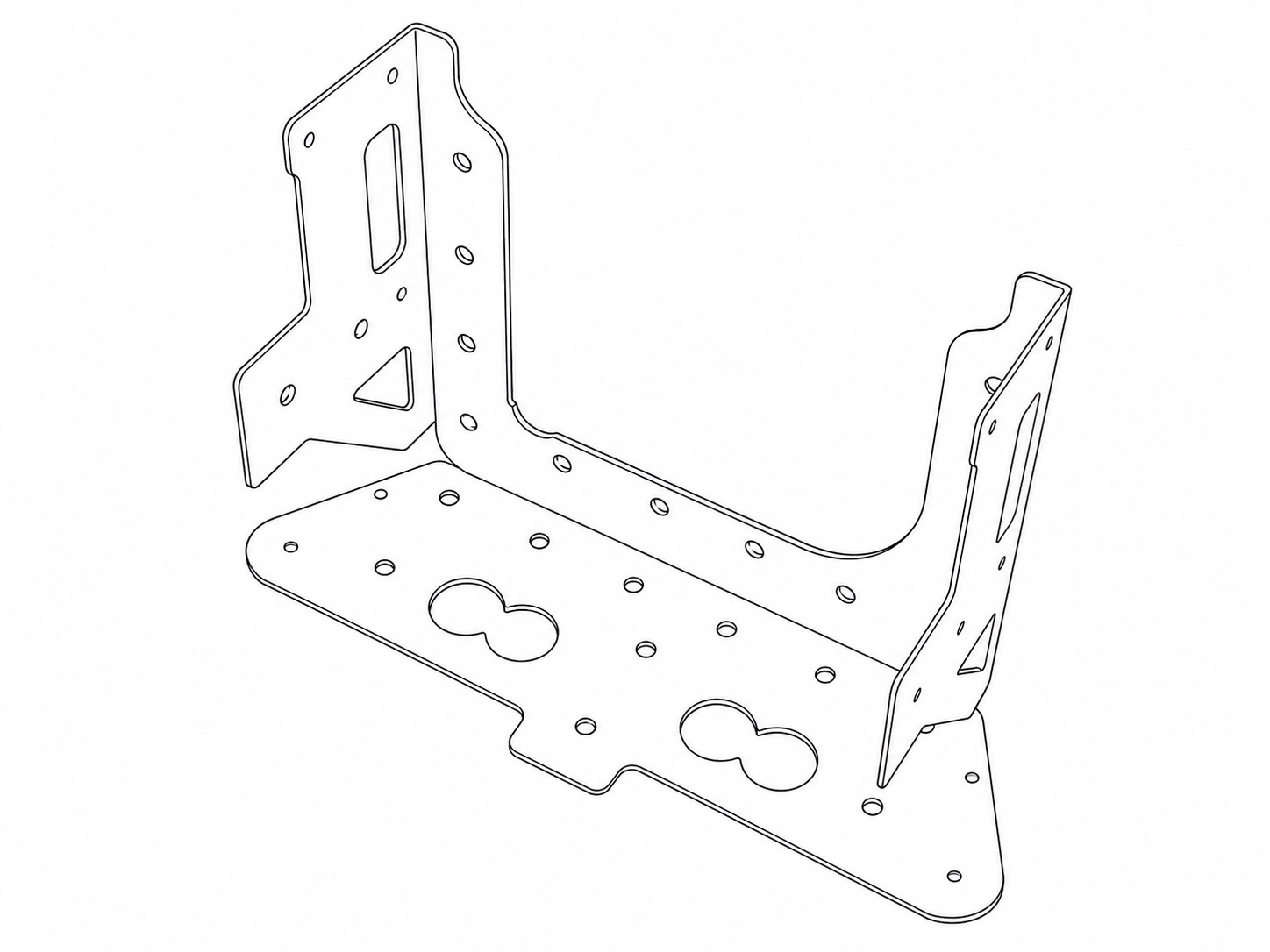 |
Frame Base | 1 | The primary central part of the Quick Deploy Frame. Two screws secure it to the bottom of the camera housing. |
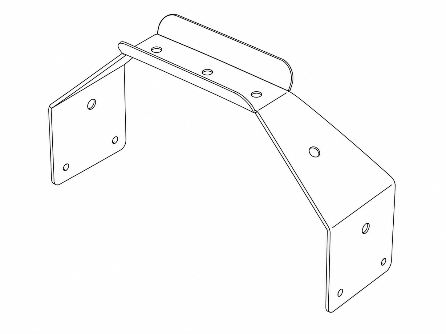 |
Frame Handle | 1 | Quick Deploy Frame Handle. |
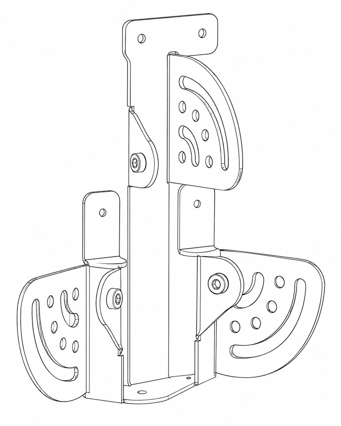 |
Left Bracket | 1 | Attaches to the left side of the Frame Base when looking towards the front face of the frame. Provides pivoting attachment point for legs and arms. |
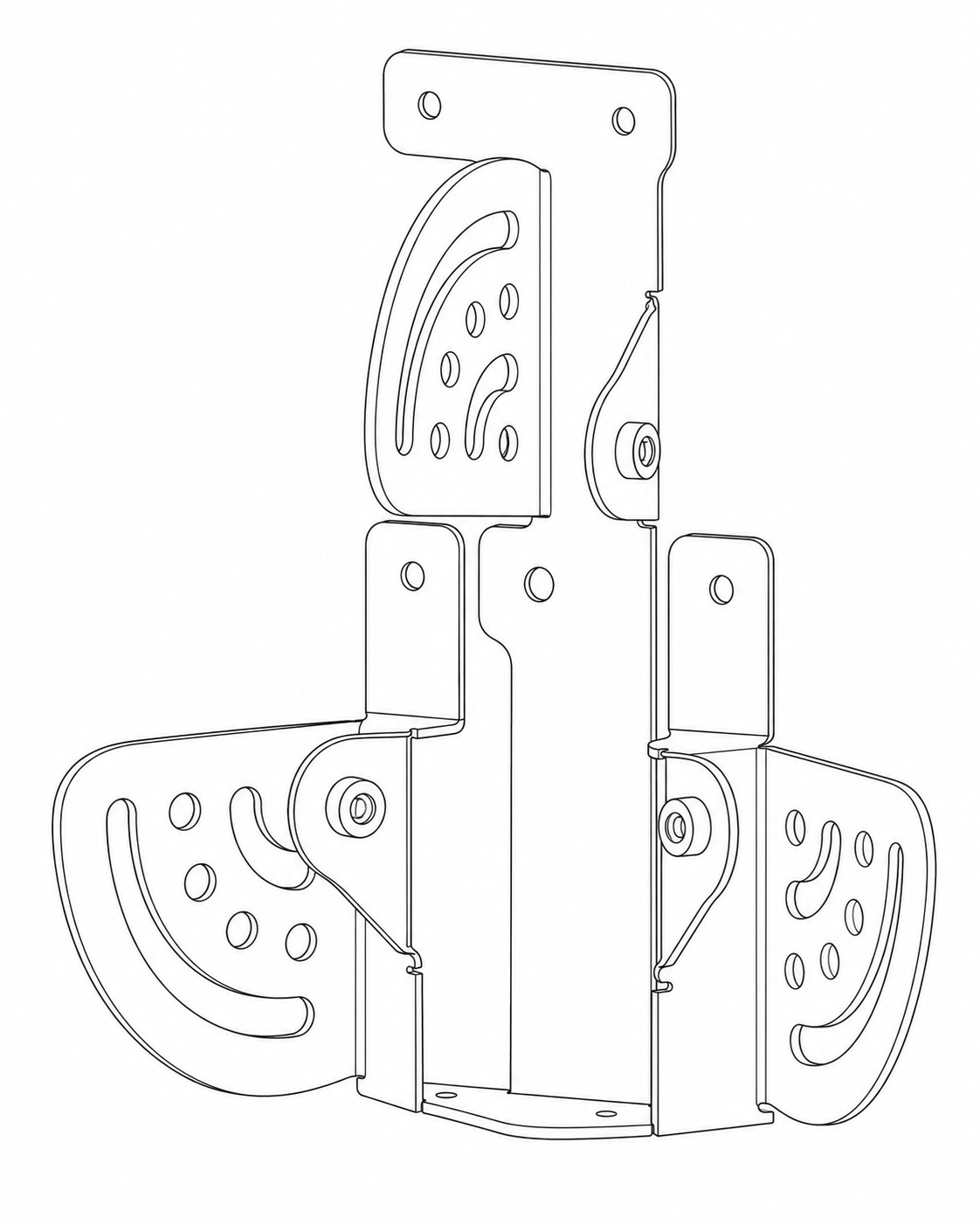 |
Right Bracket | 1 | Attaches to the right side of the Frame Base when looking towards the front face of the frame. Provides pivoting attachment point for legs and arms. Two screws secure it to the side of the camera housing. |
2. Quick Deploy Tubes Pack
A pack containing:
| Image | Part Name | Quantity | Purpose |
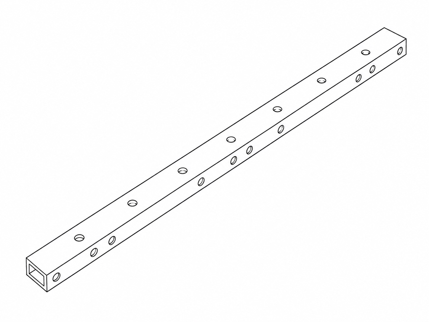 |
300mm Tube | 4 | Four legs. |
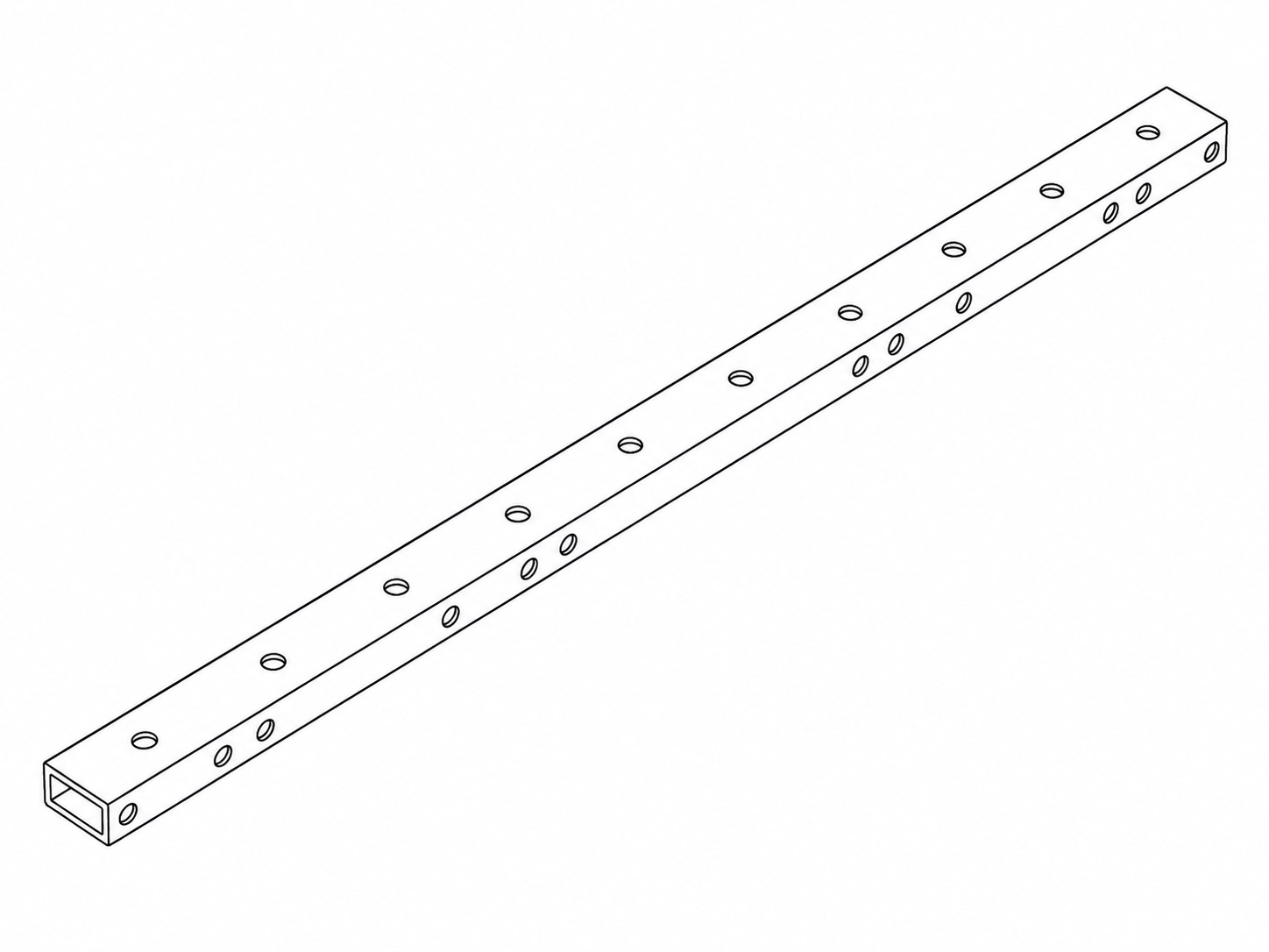 |
400mm Tube | 2 | Two pivoting arms for the flashes. |
3. Quick Deploy Fasteners Pack
A bag containing:
| Image | Part Name | Quantity | Purpose |
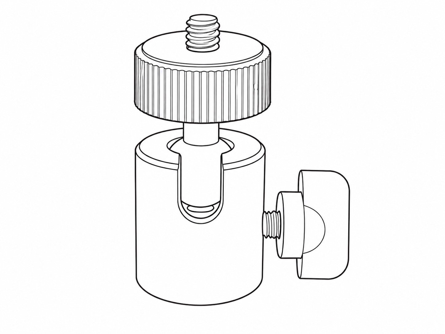 |
Mini Ball Head | 3 | For mounting the two flash housings and the PIR sensor. |
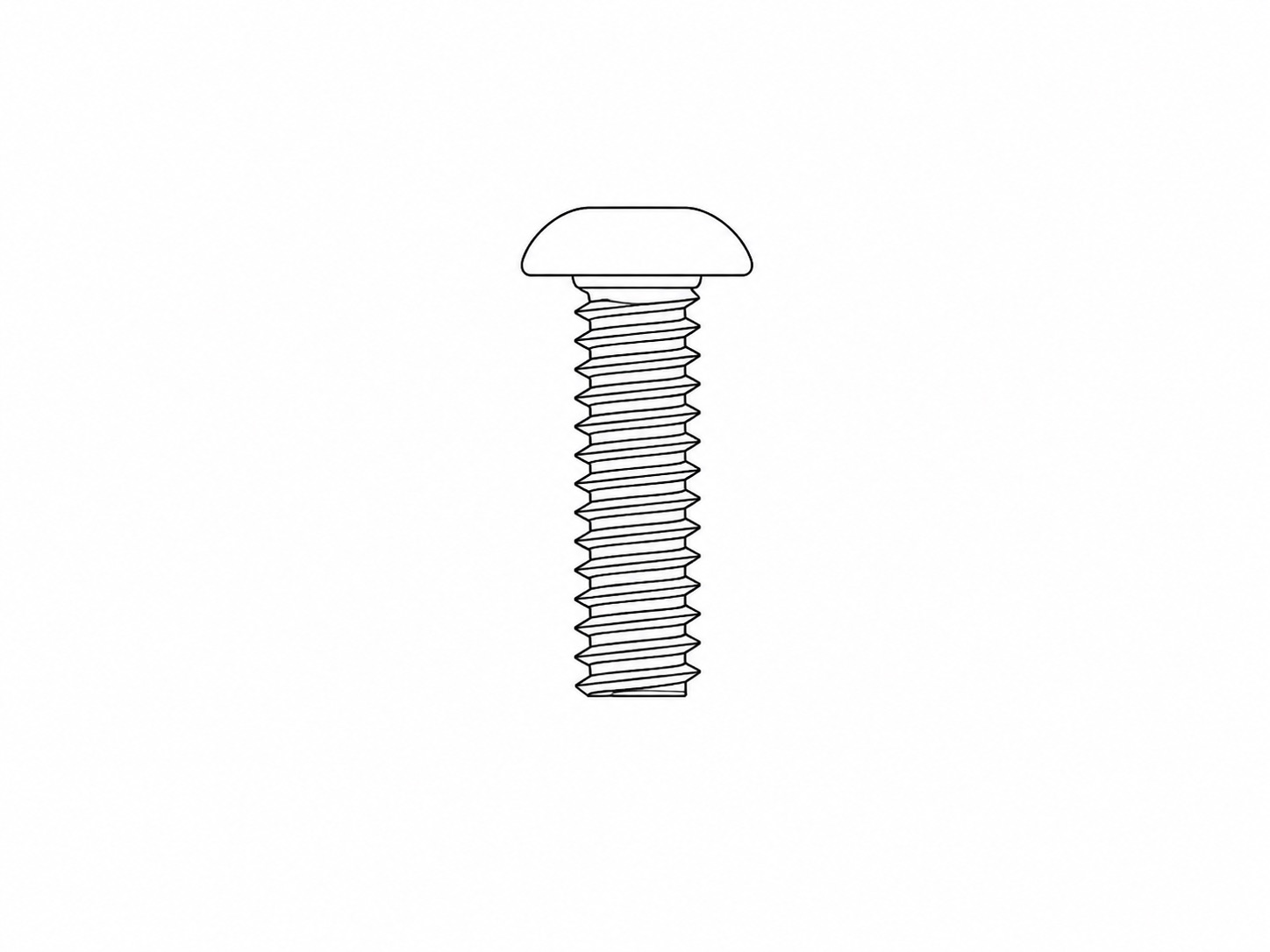 |
3/4 Inch Button Head Screw
|
3 | Two of these are for mounting the Mini Ball Heads for the flashes. One extra is supplied for optionally mounting the PIR's Mini Ball Head on a leg or arm. |
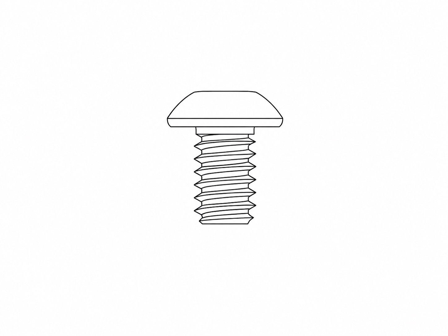 |
5/16 Inch Button Head Screw
|
3 | The shortest button head screw in the pack. One for mounting the PIR's Mini Ball Head on the Frame Handle. Two for securing the bottom of the Camera Housing to the Frame Base. |
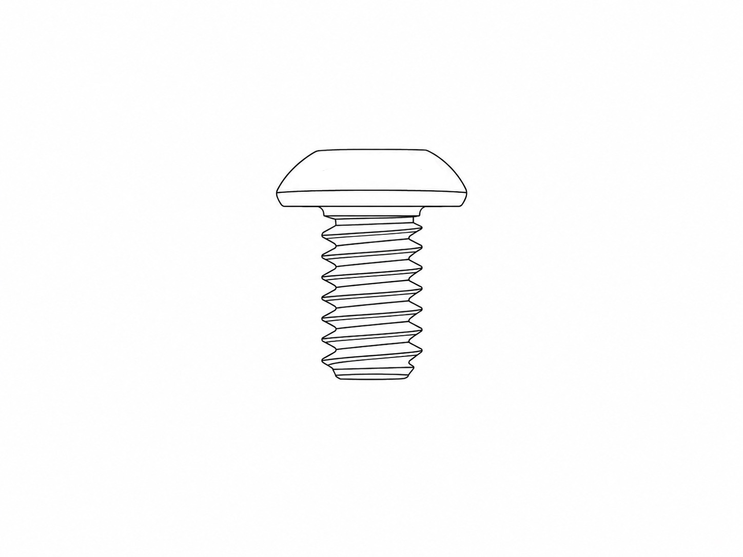 |
3/8 Inch Button Head Screw
|
2 | For securing the side of the Camera Housing to the Frame Base and Right Bracket. |
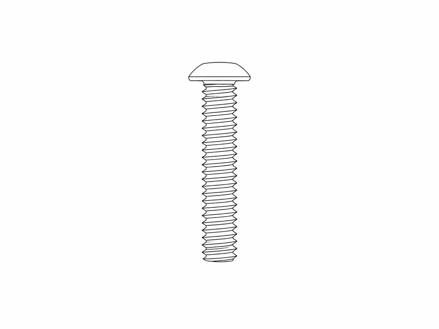 |
1.25 Inch Button Head Screw
|
6 | Attaches each arm and leg to the left and right brackets. The legs and arms pivot on these screws. |
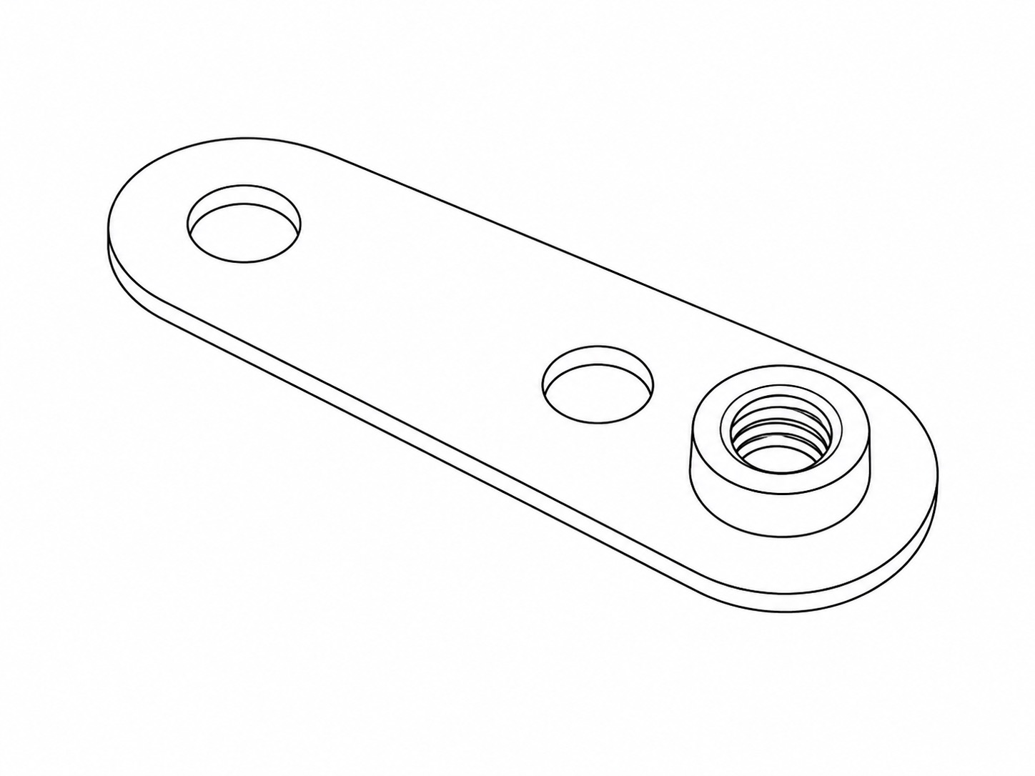 |
Friction Plate
|
6 | Part of the pivoting assembly for each arm and leg. Each 1.25 Inch Thumbscrew fastens into the thread on these Friction Plates to secure the arms and legs. |
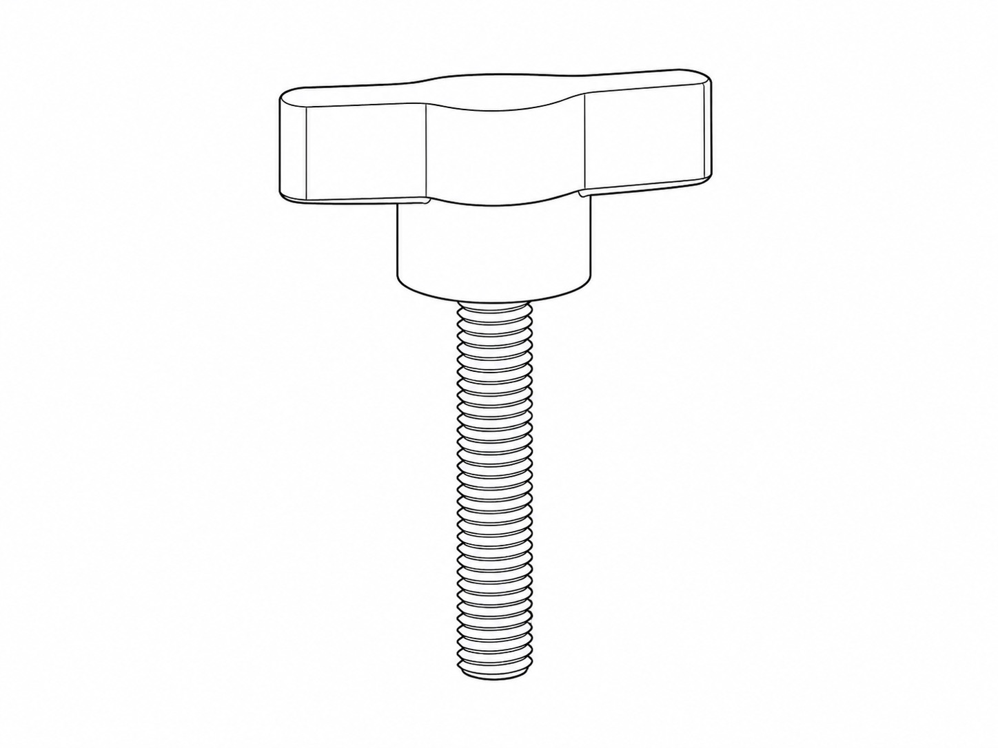 |
1.25 Inch Thumbscrew
|
6 | The primary adjustment and clamping screw for each arm and leg. |
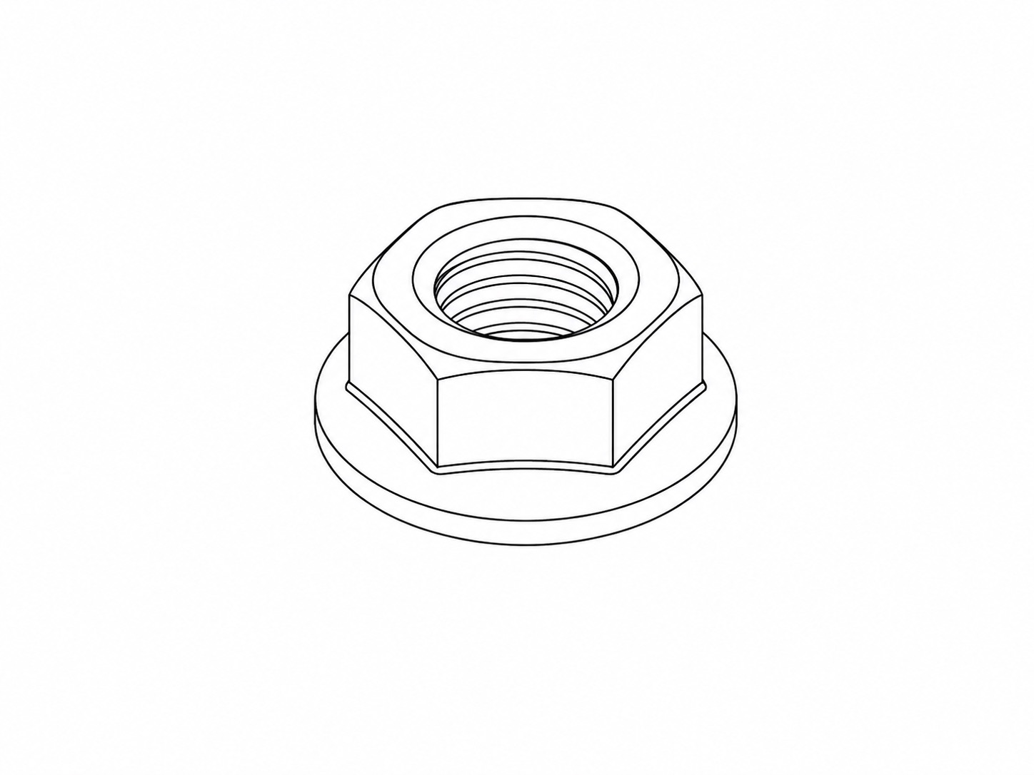 |
Serrated Nut
|
6 | Optional nuts for allowing the Thumbscrews to fasten through the pre-defined holes in the Left and Right Brackets + Friction Plates, in order to create a more locked/anti-slip assembly. |
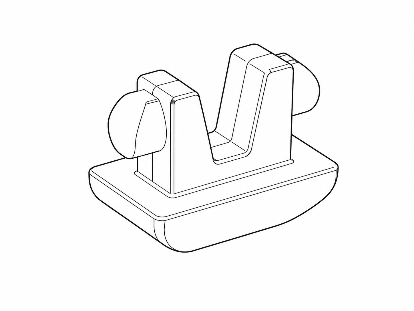 |
Rubber Foot
|
4 | A rubberised foot for the bottom of each leg. |
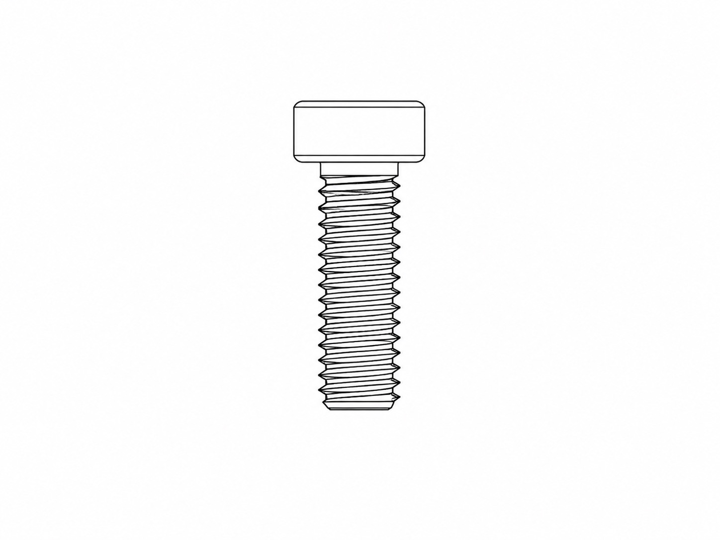 |
M4 10mm Cap Head Screw
|
12 | For fastening the Left Bracket and Right Bracket to the Frame Base and Frame Handle. |
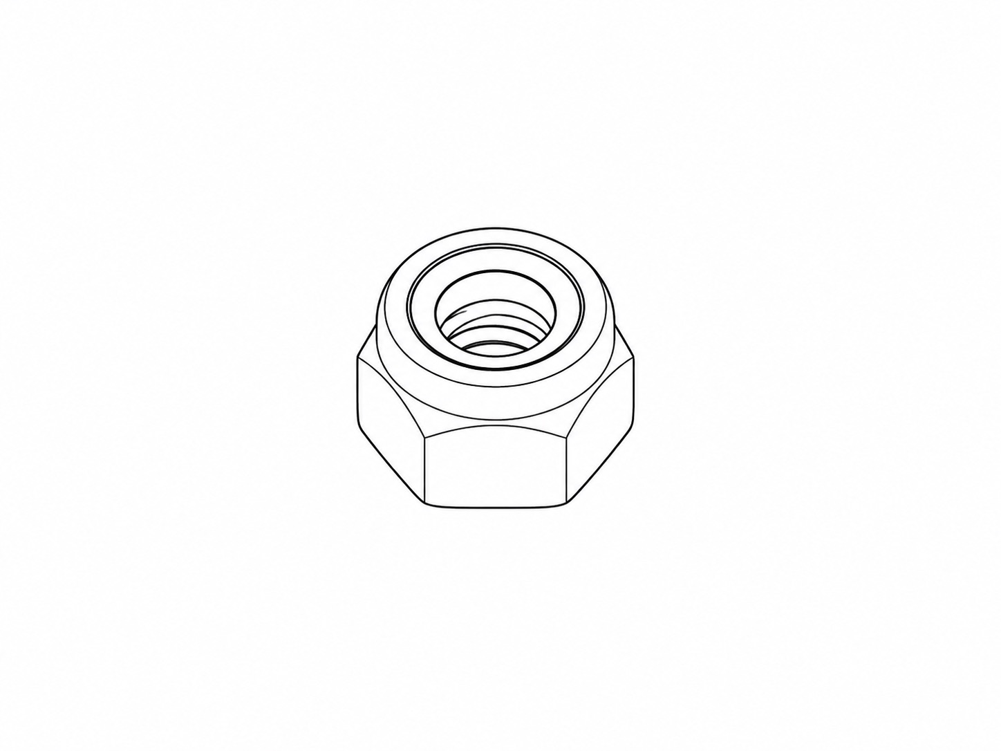 |
M4 Nut
|
12 | For fastening the Left Bracket and Right Bracket to the Frame Base and Frame Handle. |
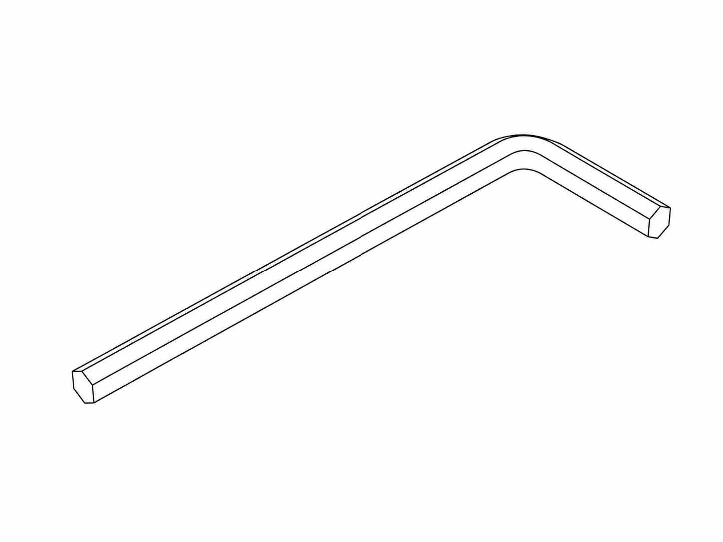 |
4mm Hex Key
|
1 | For initial assembly of the Quick Deploy Frame (fastening all of the Button Screws). |
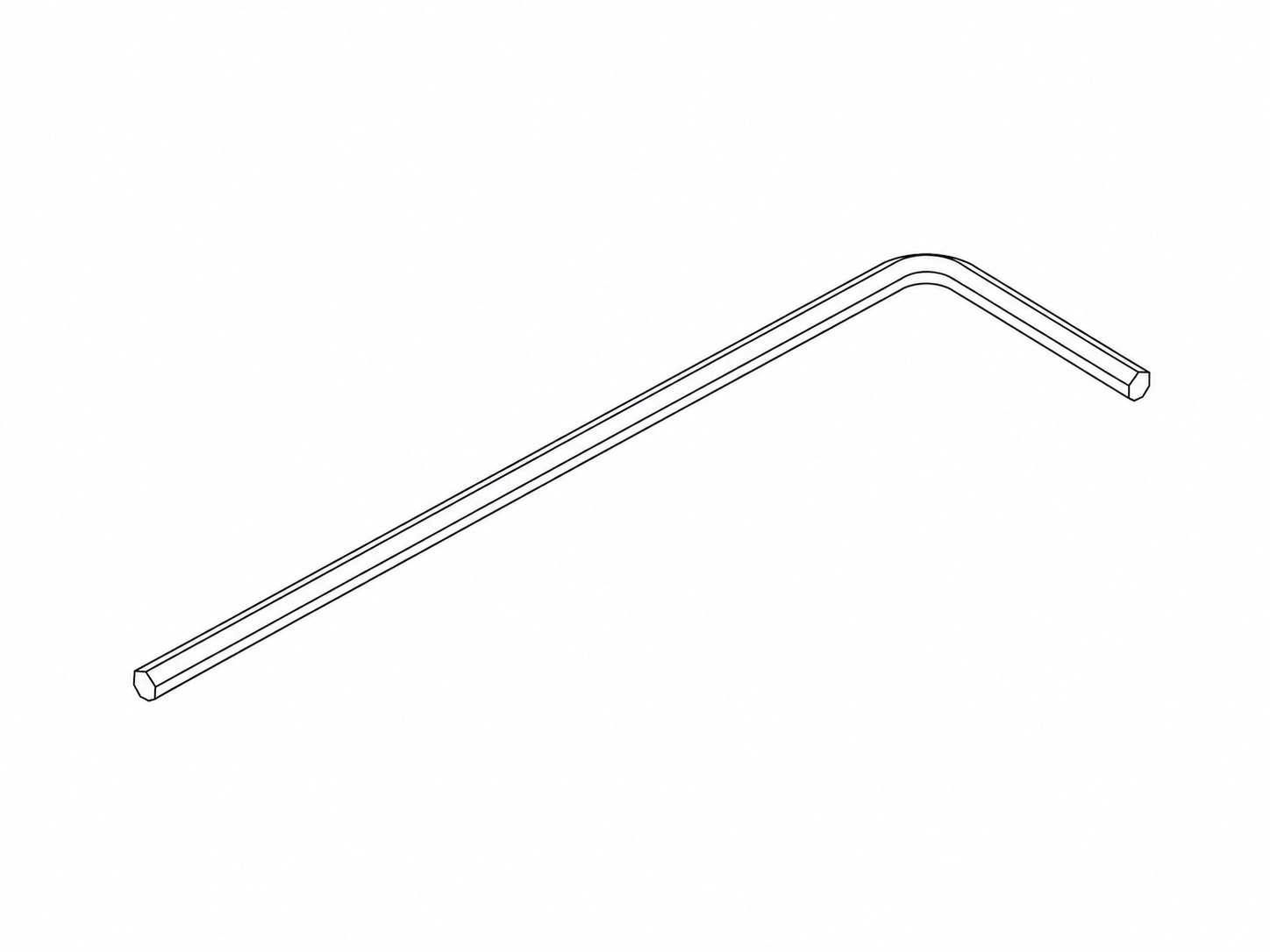 |
2.5mm Hex Key
|
1 | For initial assembly of the Quick Deploy Frame (fastening the M4 screws and nuts). |
4. Other Equipment
| Image |
Part Name |
Quantity |
Purpose |
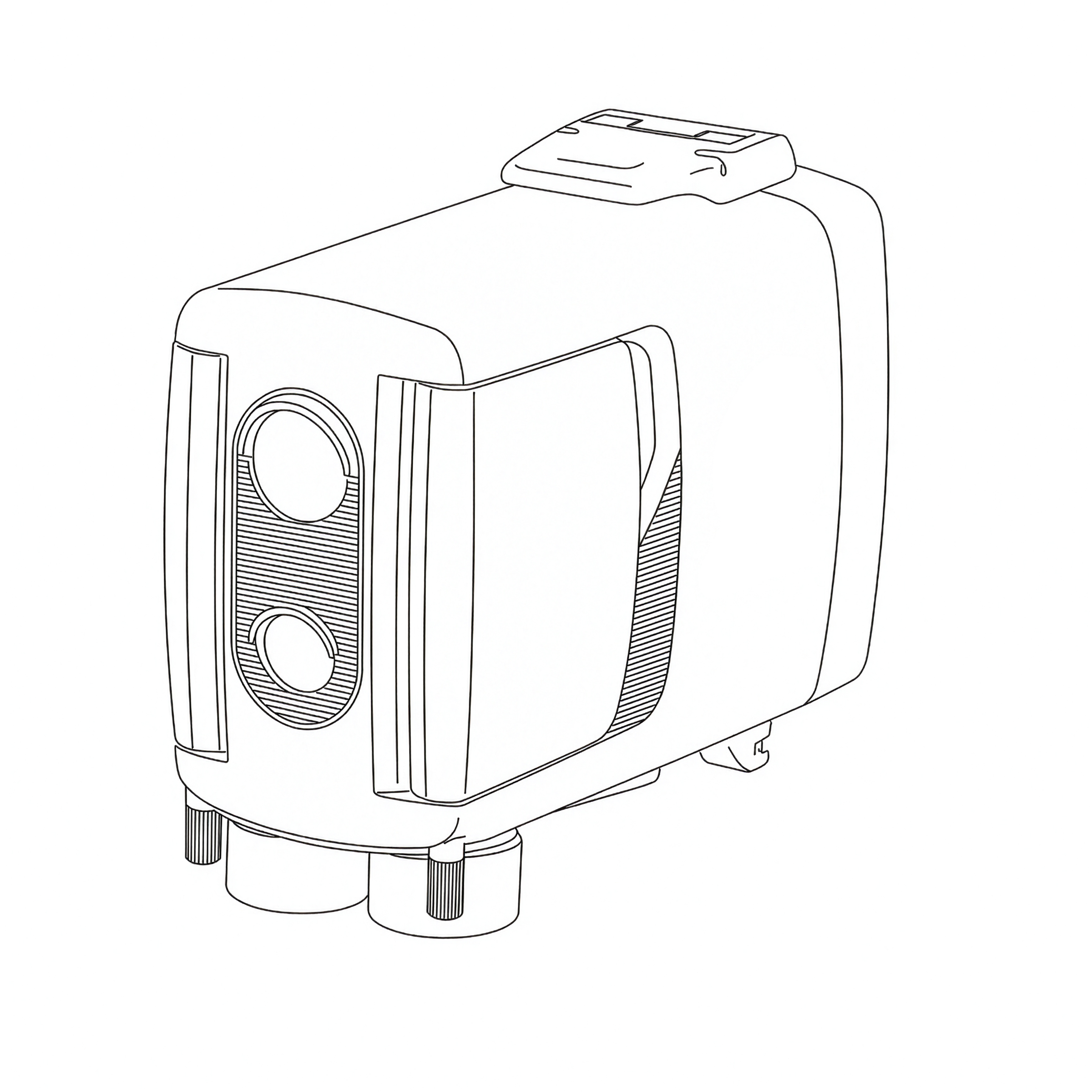 |
PIR Motion Sensor v4 | 1 | Detects motion and triggers the camera to take a photo. |
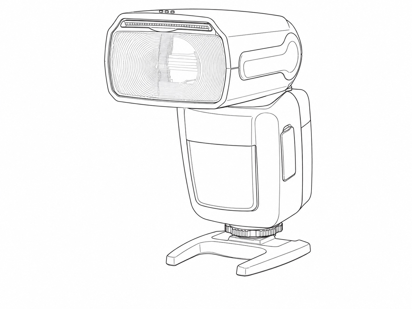 |
Z Pro Camera Trap Flash | 2 | Provides illumination in darker conditions and during the night. |
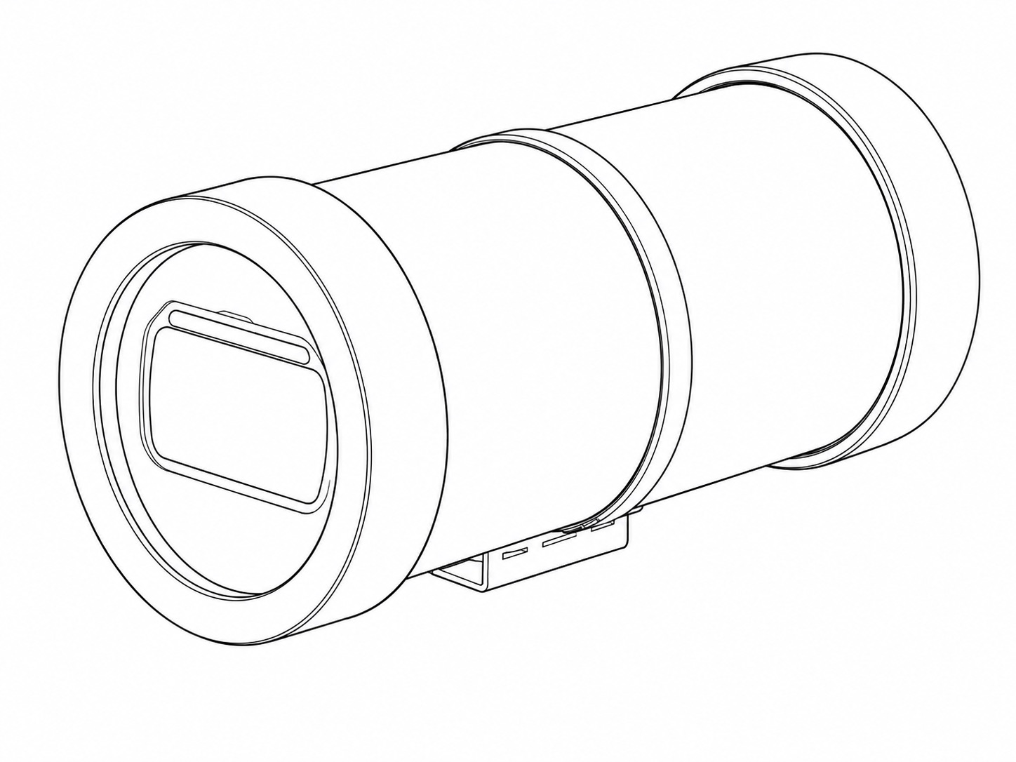 |
Flash Housing | 2 | Provides physical and weather protection for the Z Pro Flashes. |
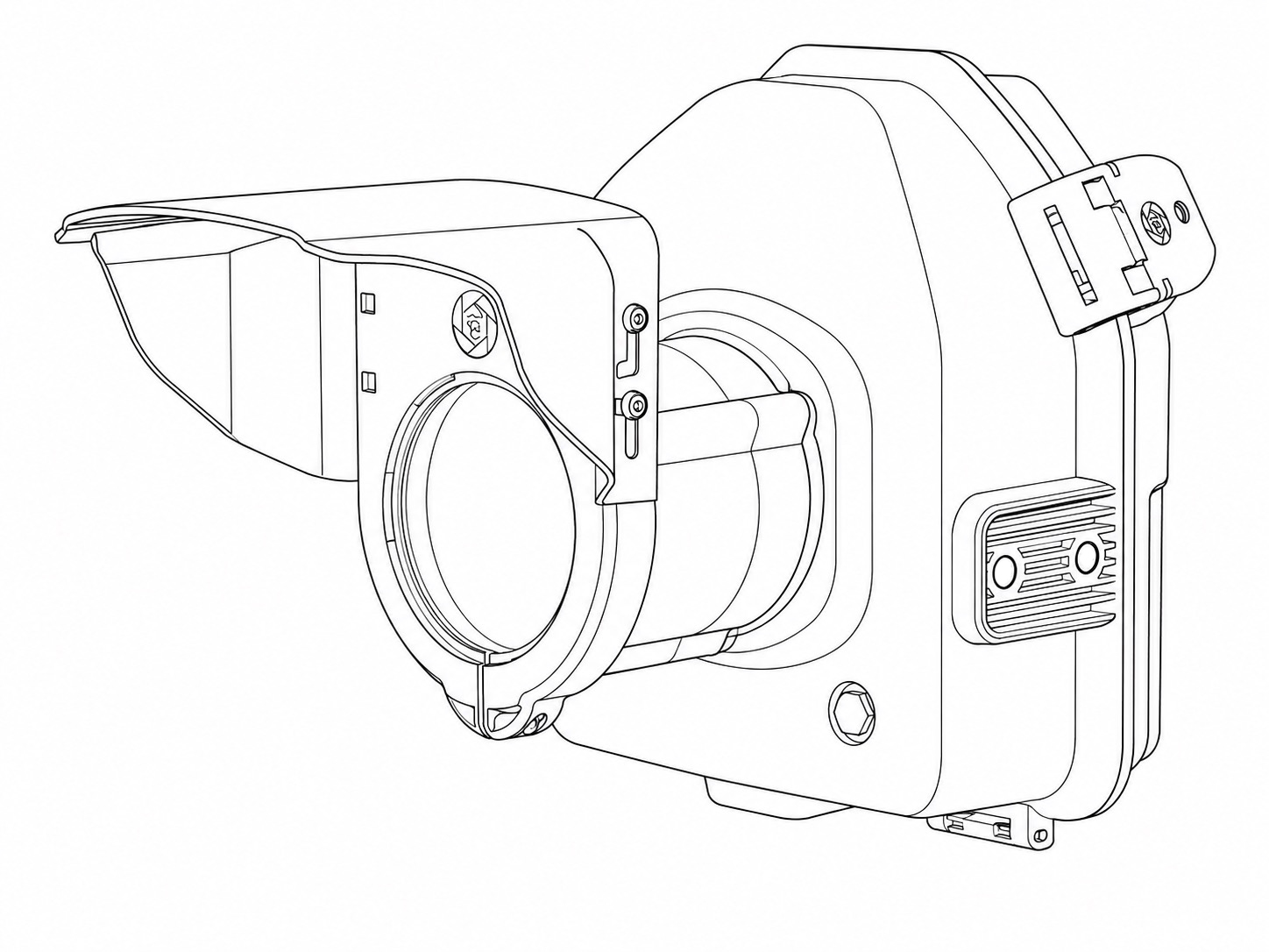 |
Camera Housing | 1 | Provides physical and weather protection for the camera. |
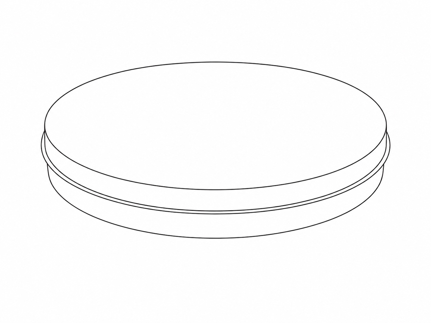 |
Camera Housing Glass Window | 1 | Part of the assembled Camera Housing. |
Wireless-only Components
1. Wireless Trigger Equipment
| Image |
Part Name |
Quantity |
Purpose |
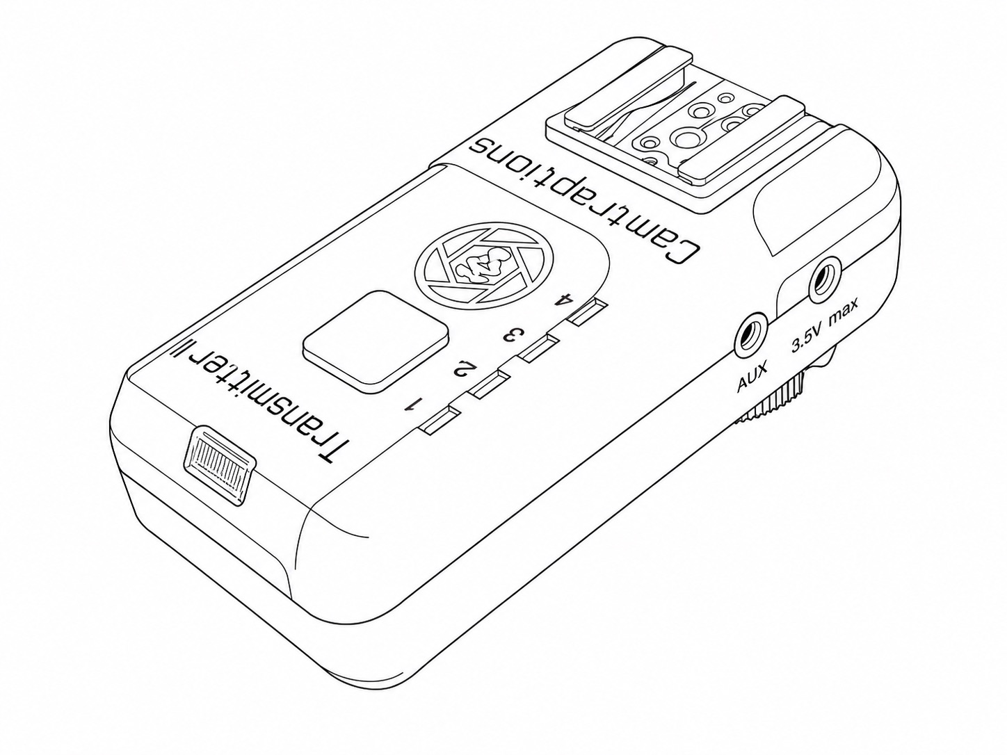 |
Wireless Transmitter v2 | 1 | Mounted directly in the camera's flash hot shoe. Sends wireless flash trigger signals to the two Receivers mounted on the two Z Pro Flashes. |
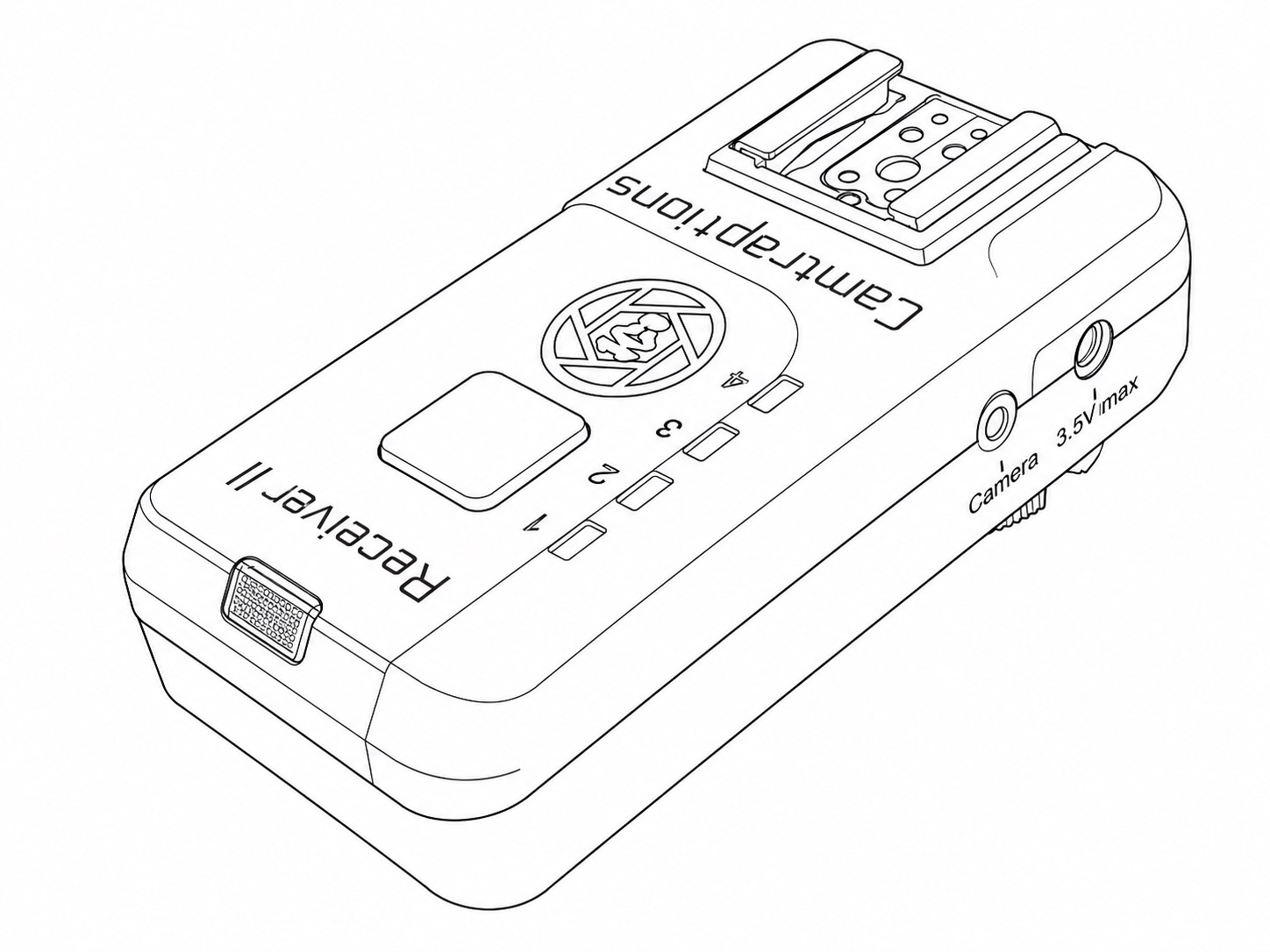 |
Wireless Receiver v2 | 3 | One Receiver is loose inside the Camera Housing and connected to the camera's shutter release socket via a Camera Connecting Cable (sold separately). Each of the other two Receivers is mounted on a Z Pro Flash. |
 |
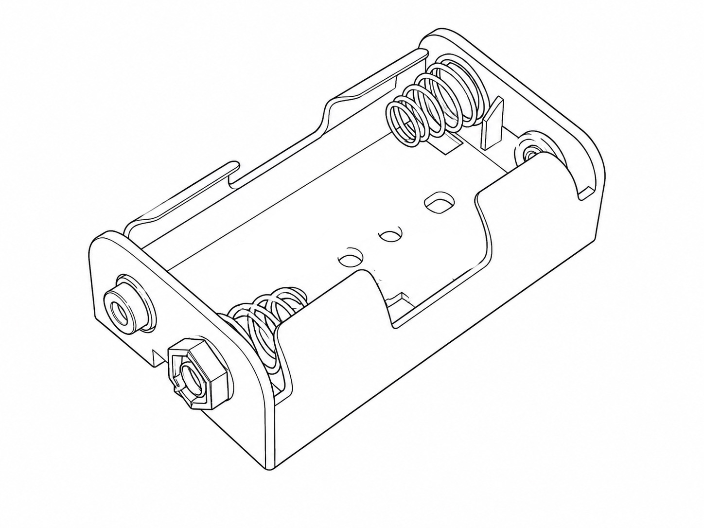
|
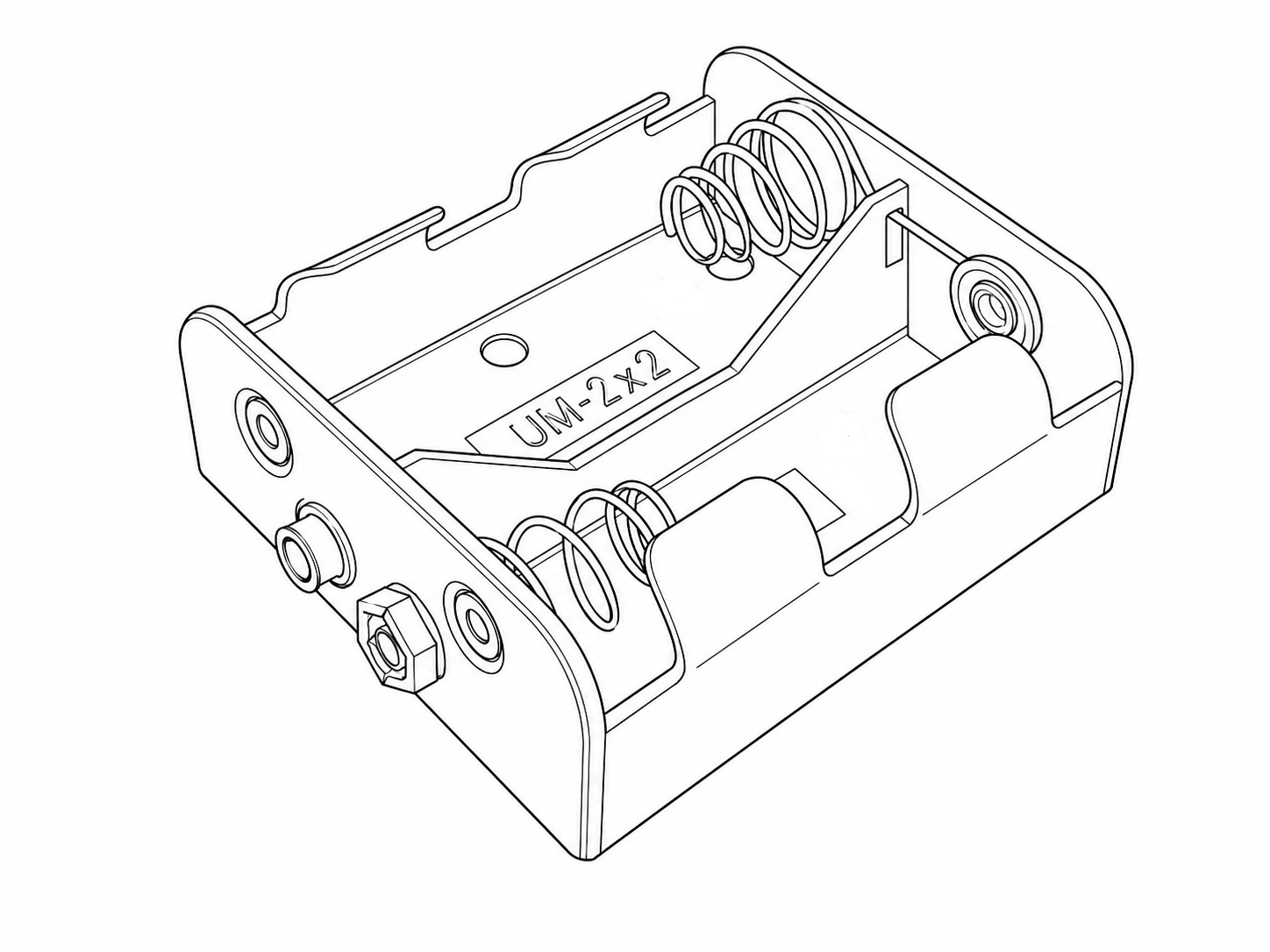
3 | Can be optionally plugged into the wireless triggers to power them using C size cells for around two months of life. |
 |
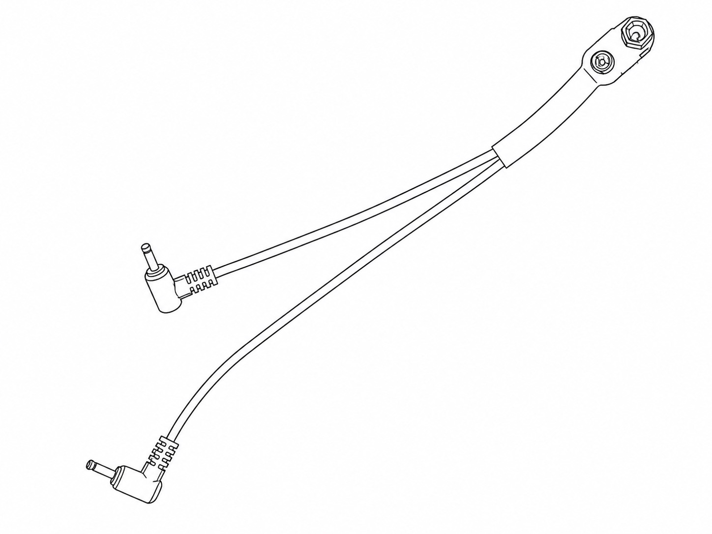
|
3 | Can be optionally plugged into the wireless triggers to power them using AA size cells for around two weeks of life. |
 |
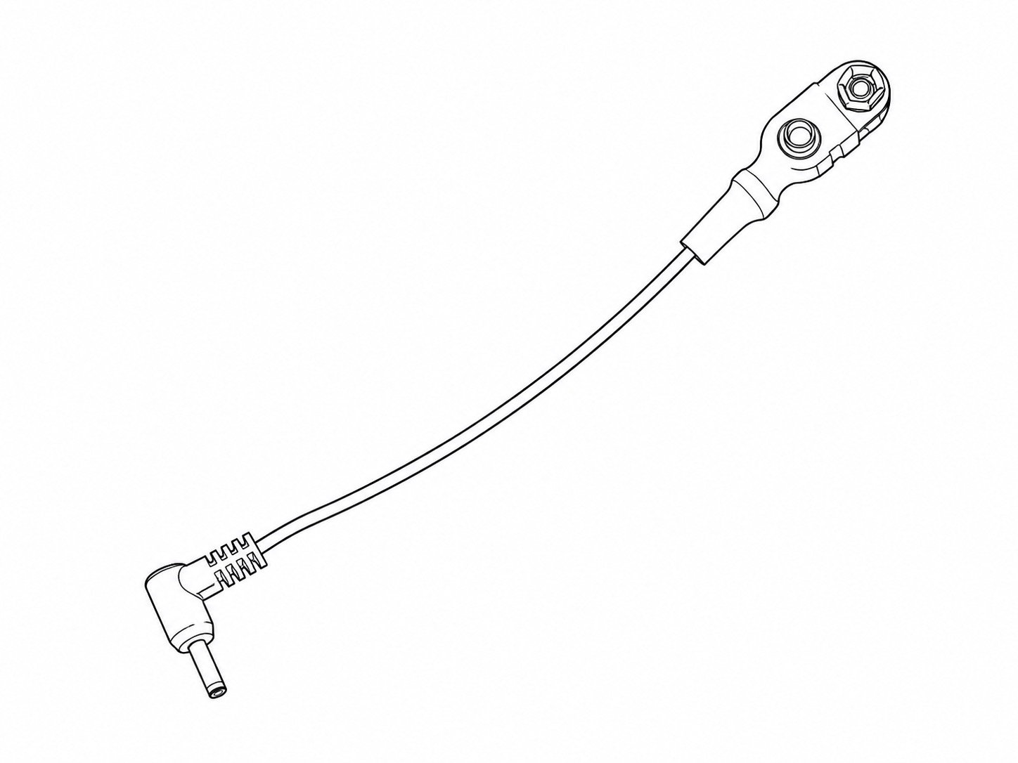
|
1 | Connects one 2xC or 2xAA Battery Holder to the Transmitter and Receiver contained inside the Camera Housing. |
 |
|
2 | Connects one 2xC or 2xAA Battery Holder to the Receivers mounted on each Z Pro Flash. |
Wired-only Components
1. Quick Deploy Cables Pack
A bag containing:
| Image |
Part Name | Quantity |
Purpose |
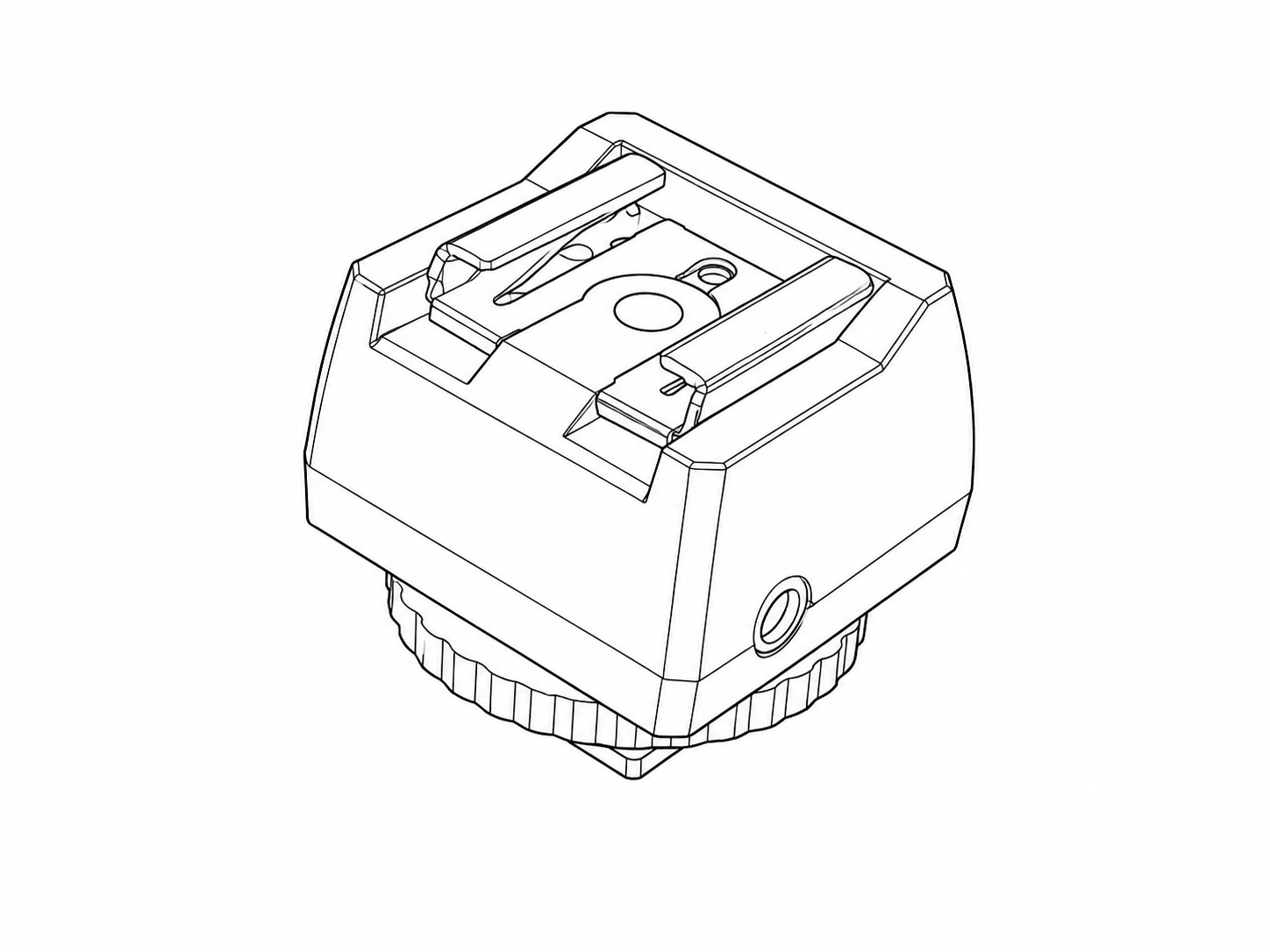 |
Flash Hot Shoe Adapter
|
1 | Mounted directly in the camera's flash hot shoe. Transfers the camera's "flash shoot" signals into the cable system. |
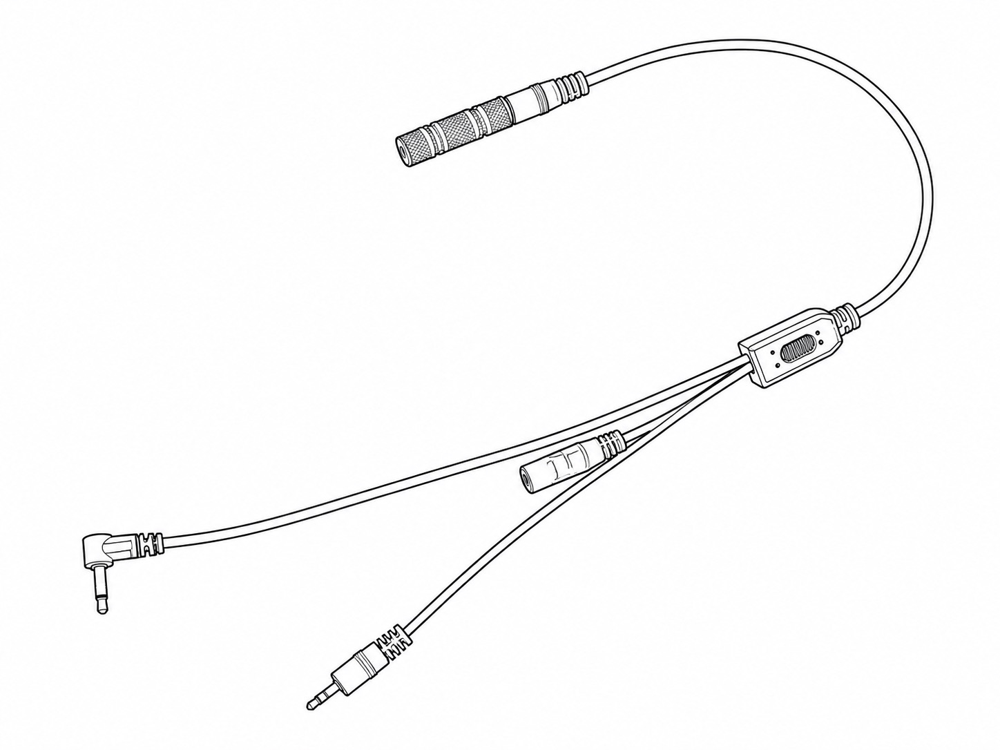 |
Wired Z Pro Flash Adapter
|
1 | Important for ensuring that the Z Pro Flashes are woken up from sleep and triggered reliably. |
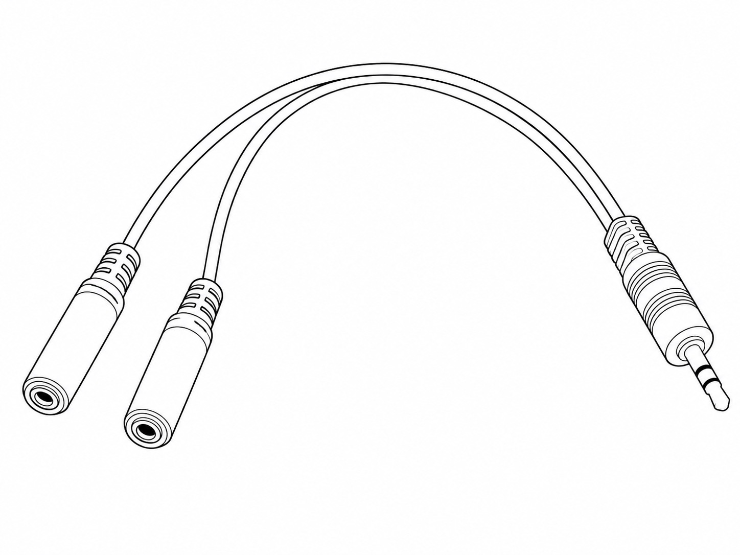 |
2 Way Flash Splitter
|
1 | Connects from the Wired Z Pro Flash Adapter to the two Waterproof Flash Signal Cables. |
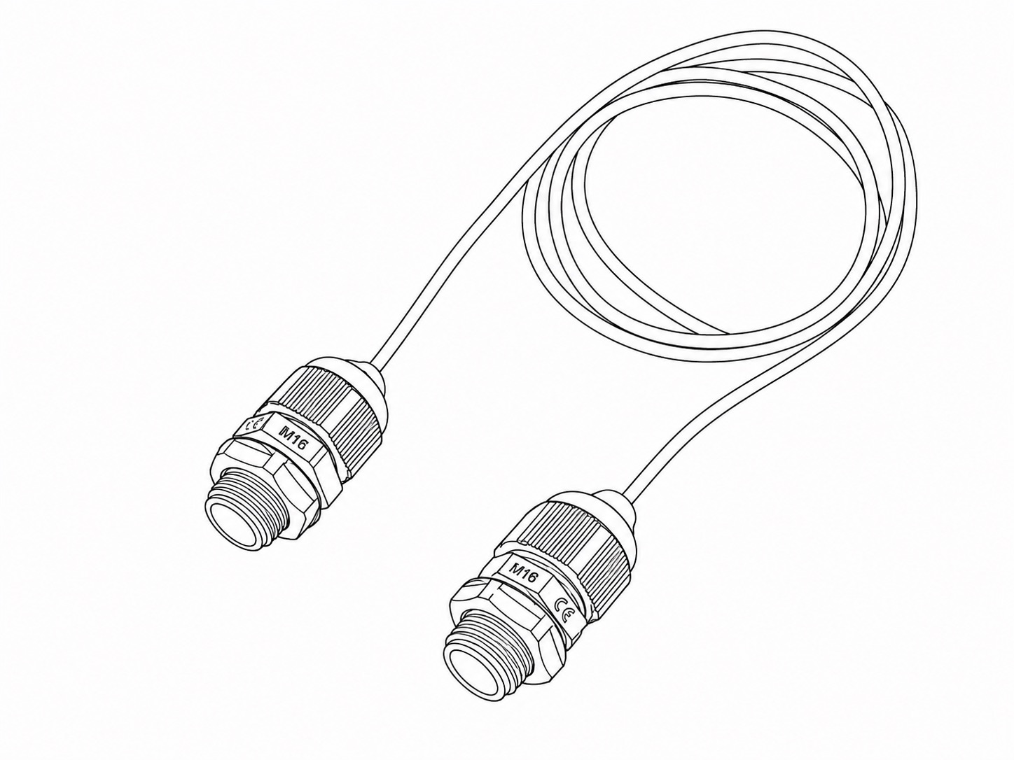 |
Waterproof Flash Signal Cable | 2 | Transfers the flash signals from the Camera Housing to the two Flash Housings. |
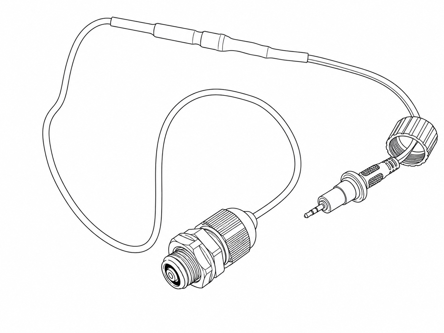 |
Waterproof PIR Signal Cable | 1 | Transfers the PIR Sensor's trigger signals to the Camera Housing. |
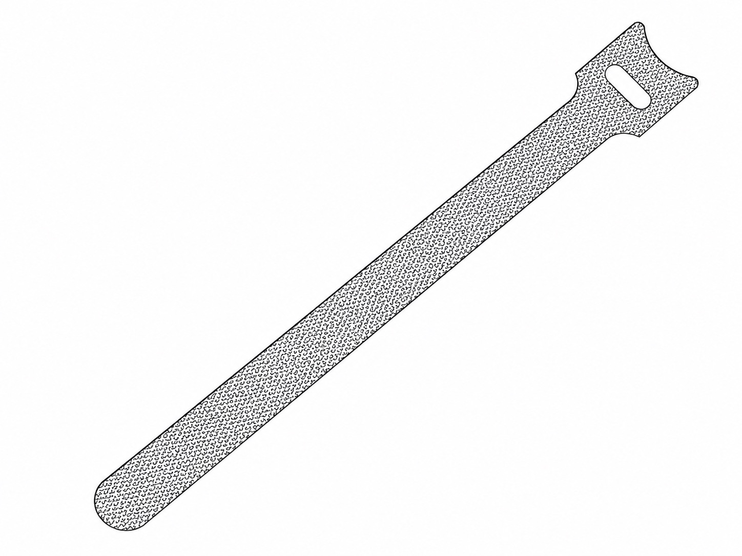 |
Hook-and-loop Cable Tie | 5 | Provided to keep the cabling neat and secure. |
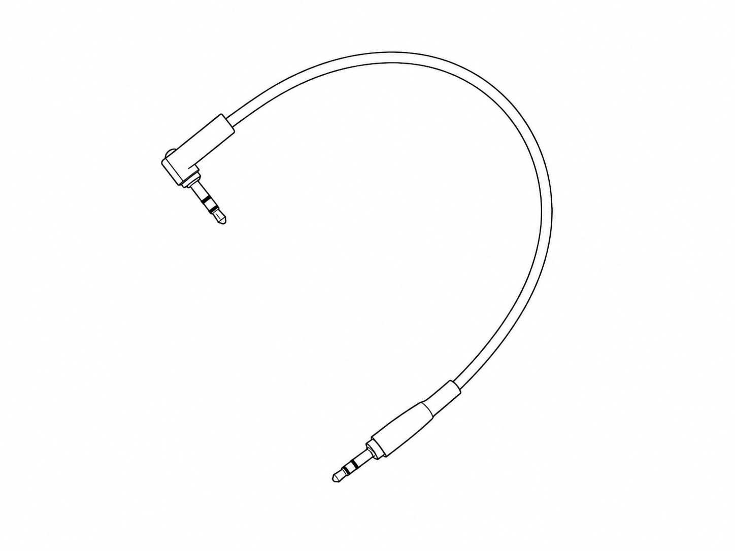 |
20cm Flash Cable | 2 | Contained within each Flash Housing. Connects from the Waterproof Flash Signal Cable to the sync socket on the side of each Z Pro Flash. |
Assembly Instructions
Information on how to assemble the Quick Deploy Camera Trap system.
Assembling the Quick Deploy Frame
Before beginning assembly, lay out all Quick Deploy Frame components on a clear surface. The initial assembly requires the supplied 2.5 mm and 4 mm Hex Keys, plus an adjustable wrench or thin nose pliers (not supplied). Do not fit the camera housing, flashes or PIR motion sensor until the frame has been fully assembled and checked for stability.
1. Assemble the Main Frame
Place the Frame Base on a flat surface with the front of the Frame Base facing down.
As you are look down on the inside of the Frame Base, position the Left Bracket on the right-hand side of the Frame Base and the Right Bracket on the left-hand side.
Position the Frame Handle between the upper ends of the Frame Base and the Left and Right Brackets. The ends of the Frame Handle should sit on the inside of the Frame Base.
Use the twelve M4 10 mm Cap Head Screws and twelve M4 Nuts to fasten the Left Bracket and Right Bracket to the Frame Base and Frame Handle. The twelve fastening points are shown in the image below and they correspond to the twelve smaller-diameter holes in the frame parts. Tighten the fixings using the supplied 2.5 mm Hex Key and an adjustable wrench or thin-nose pliers to hold the nuts securely while you tighten the screws. Position the nuts on the inside of the frame - the screws should fasten inwards from the outside.
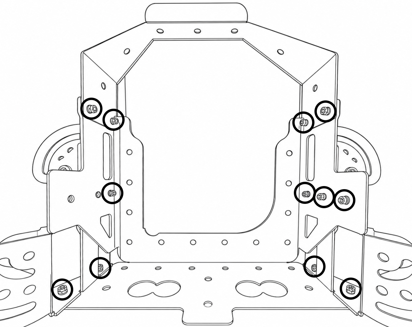
Check that the main frame is fully secure before continuing.
2. Fit the Legs
Push one Rubber Foot onto the end of each 300 mm Tube. It is recommended to push the Rubber Foot on at an angle rather than trying to squeeze both rubber lugs through at the same time. Make sure the rubber lugs are fully engaged and secure inside the tubes.
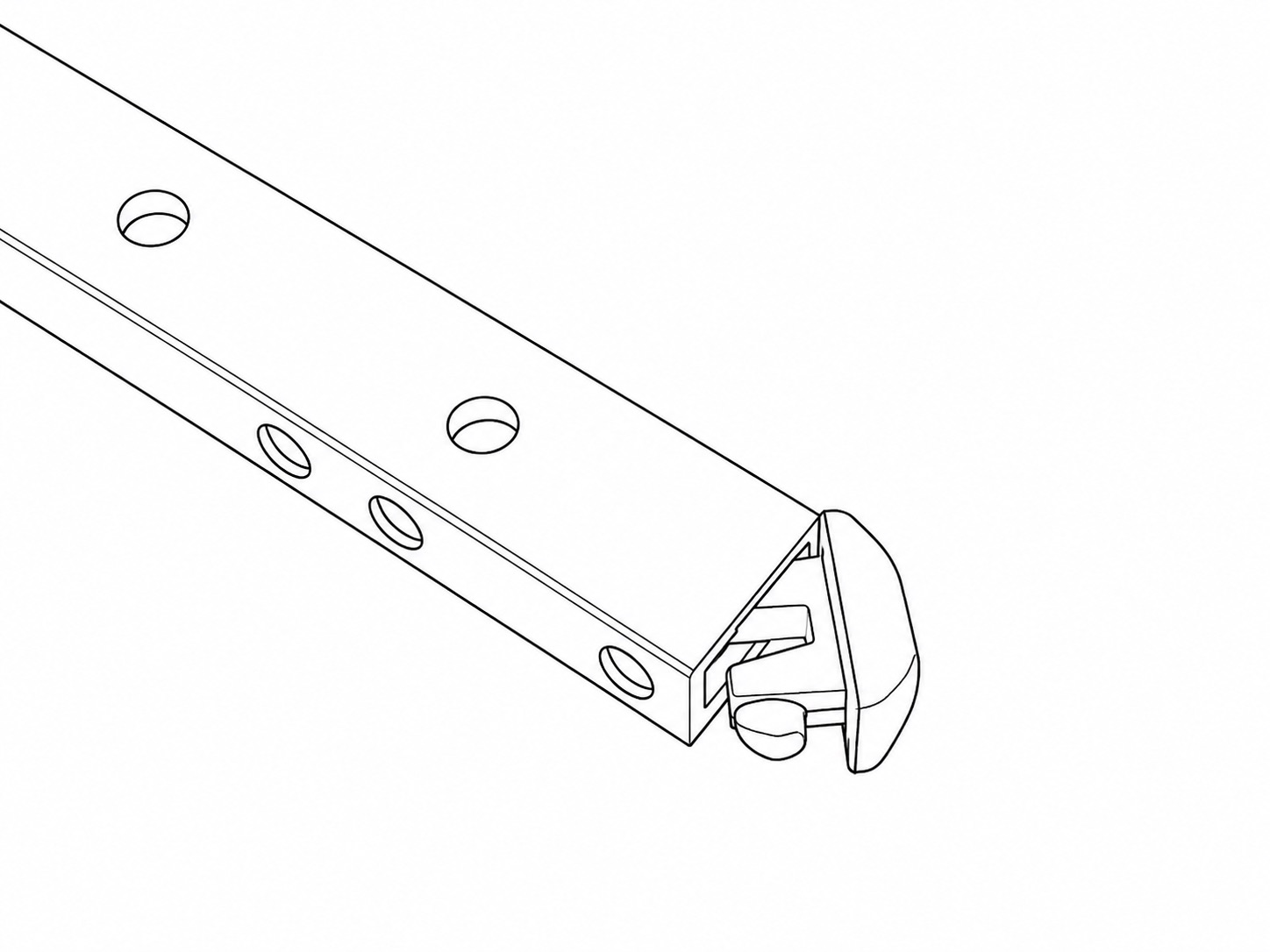
Attach two legs to the Left Bracket and two legs to the Right Bracket using the pivoting assemblies.
For each leg, use:
Fit each leg so that it can pivot outwards from the bracket. Tighten the Thumbscrew sufficiently to hold the leg in position while still allowing it to be adjusted during setup. The 1.25 Inch Button Head Screws should be kept loose enough that the leg can freely pivot around it, while the 1.25 Inch Thumbscrew is responsible for securing and clamping the leg in place.
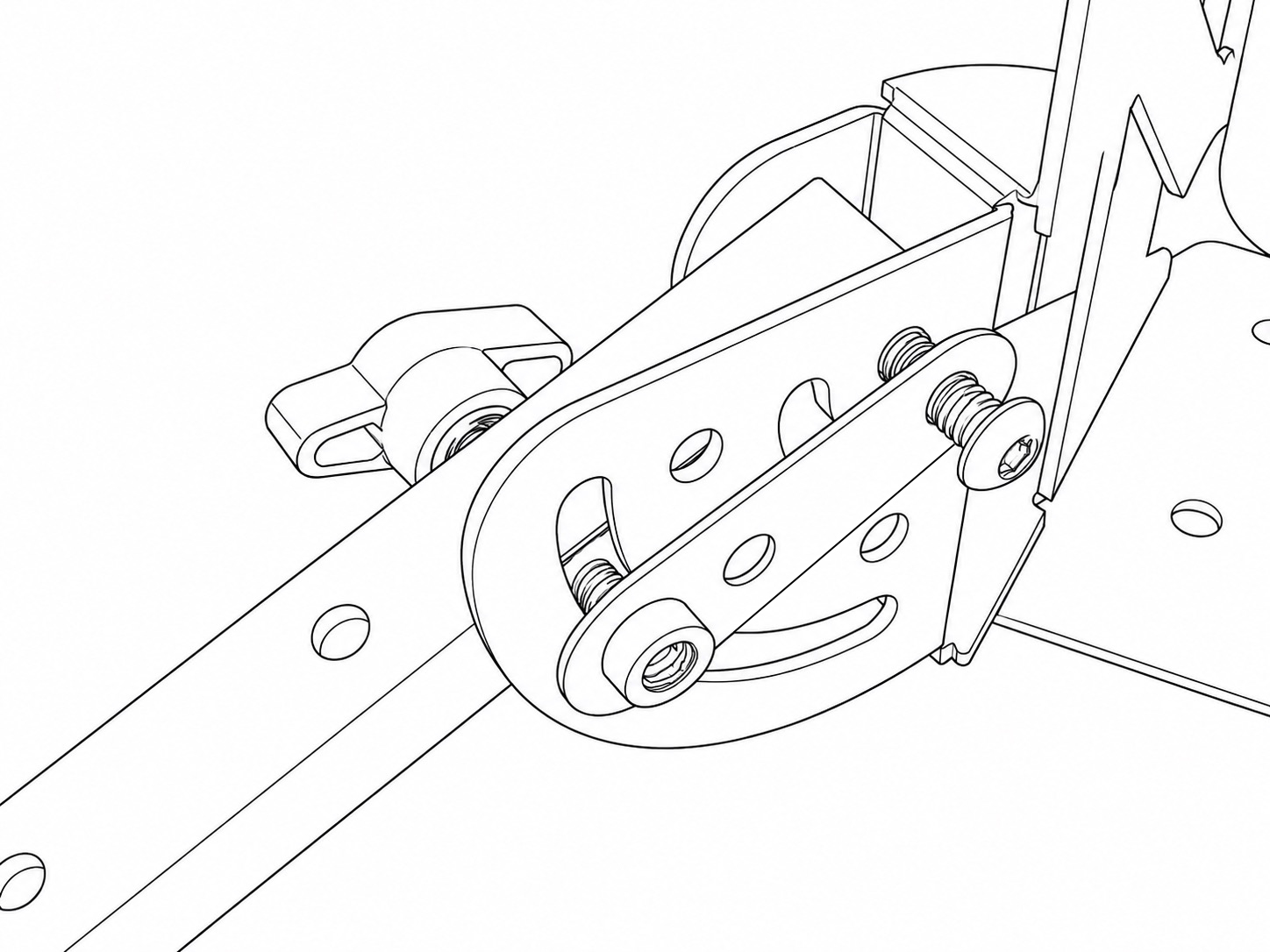
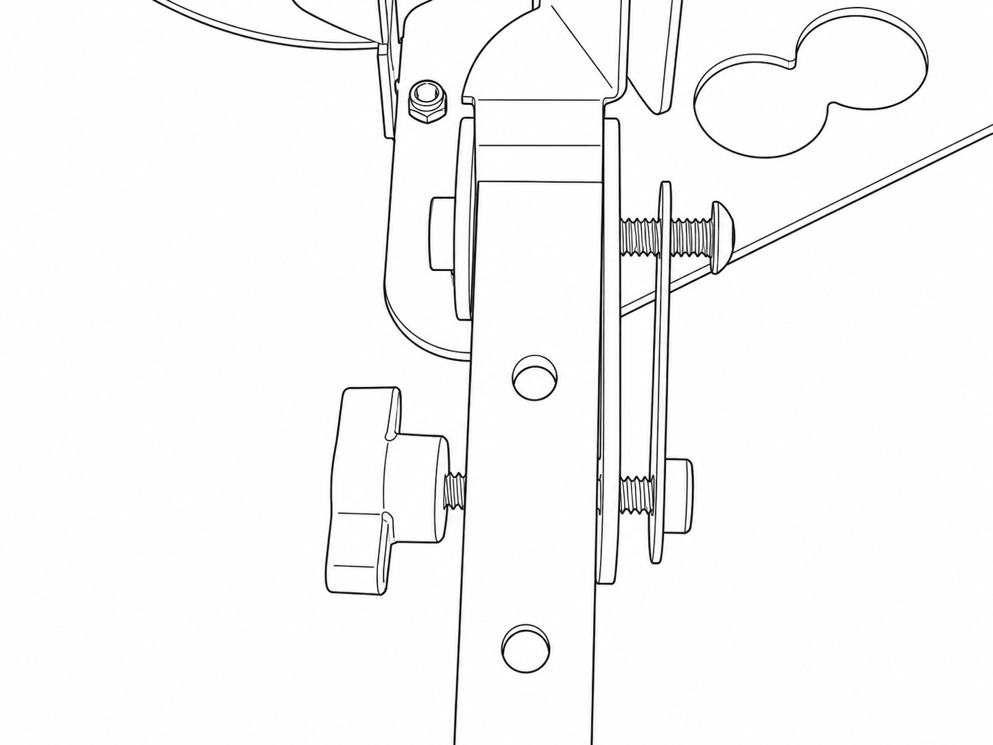
Repeat for all four legs.
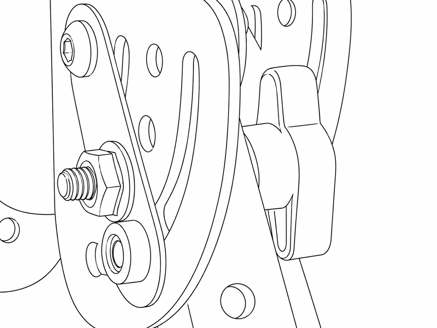
Where a more rigid anti-slip assembly is required, fasten the 1.25 Inch Thumbscrews to the supplied Serrated Nuts through the pre-defined holes in the brackets and Friction Plates.
3. Fit the Flash Arms
Attach one 400 mm Tube to each side of the frame to create the two pivoting flash arms.
Use one 1.25 Inch Button Head Screw, one Friction Plate and one 1.25 Inch Thumbscrew for each arm.
Position the arms so that they can pivot independently away from the frame. Tighten the Thumbscrews enough to hold their position securely and keep the 1.25 Inch Button Head Screws loose enough that the arm can freely pivot when the Thumbscrew is released.
4. Fit the Mini Ball Heads
Attach one Mini Ball Head to the end of each flash arm using a 3/4 Inch Button Head Screw. These Mini Ball Heads will support the two Weatherproof Flash Housings.
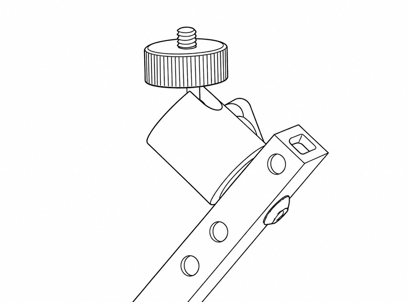
Attach the third Mini Ball Head to the Frame Handle using a 5/16 Inch Button Head Screw. This will support the PIR Motion Sensor v4.
Alternatively, the PIR Motion Sensor v4 Mini Ball Head may be mounted on a leg or flash arm using the remaining 3/4 Inch Button Head Screw, if this provides a more suitable sensor position.
Tighten the mounting screws using the supplied 4 mm Hex Key.
5. Final Frame Check
Before fitting the Camera Housing, Flash Housings and PIR Motion Sensor v4, check that:
* the Frame Base, Frame Handle and both Left and Right Brackets are securely fastened
* all four legs are stable and the Rubber Feet are properly fitted
* both flash arms are secure
* the Mini Ball Heads are securely fitted
* no components can move unexpectedly when the frame is lifted or adjusted.
Once assembled, the legs and flash arms can be repositioned in the field using the Thumbscrews.
Support the part being adjusted at all times, loosen only one fastening at a time, and retighten it fully before moving on to another adjustment.
Mounting the Camera Housing
First, assemble the Camera Housing according to its instruction manual.
Position the fully assembled Camera Housing within the centre of the frame, with the Camera Housing's Tube System facing outwards through the front of the Quick Deploy Frame.
Secure the bottom of the Weatherproof Camera Housing to the Frame Base using two 5/16 Inch Button Head Screws.
Secure the side of the Weatherproof Camera Housing using the two 3/8 Inch Button Head Screws, fastening it to the Frame Base and Right Bracket as applicable.
Tighten all four mounting screws using the supplied 4 mm Hex Key. The Camera Housing should be firmly supported, with no movement when gently tested.
Slight pressure may need to be applied to the parts when inserting the two 3/8 Inch Button Head Screws into the side of the assembly, in order to ensure proper alignment of the holes and to allow the 3/8 Inch screws to run cleanly into the threaded inserts of the Camera Housing.
Connecting the Cable System (wired version only)
1. Prepare the Camera Housing
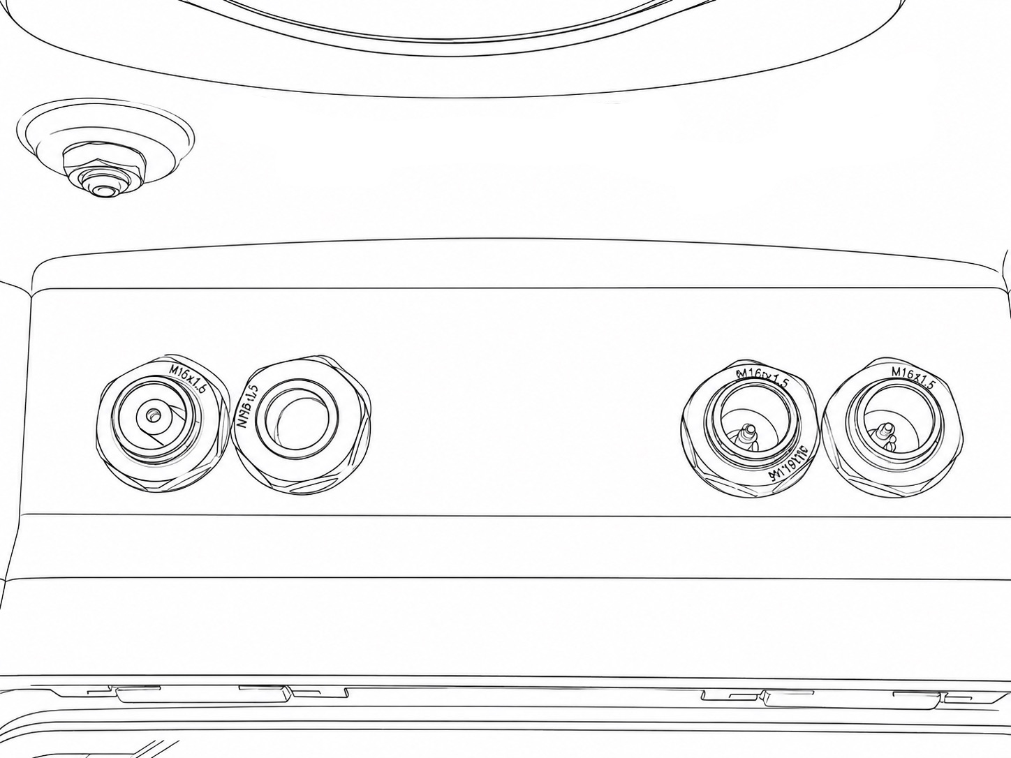
Open the Weatherproof Camera Housing and locate the four blanking plugs in the cable-entry holes on its underside.
Remove three of the four blanking plugs. Retain the remaining blanking plug in the unused hole, and keep the removed plugs in a safe place for future use.
Fit the following connectors into the open holes on the bottom of the Camera Housing:
- The waterproof female 2.5mm connector on the Waterproof PIR Signal Cable.
- The male ends of the two Waterproof Flash Signal Cables.
The nuts of the waterproof connectors must first be removed from the connector threads. Do not remove the rubber washer from the waterproof connector thread. The connectors should be pushed up into the open holes in the floor of the Camera Housing from the outside. The nuts should be re-secured back onto the threads from the inside. Tighten the nuts to apply sufficient pressure and to create a good seal with the rubber washer on the outside of the Camera Housing.
The floor of the Camera Housing should look like this:
2. Make the connections inside the Camera Housing
Fit the Flash Hot Shoe Adapter into the flash hot shoe mount of the camera. Make sure that it is oriented correctly. Once in place, secure the Flash Hot Shoe Adapter by turning the collar and locking it fully down.
Connect your Camera Connecting Cable (sold separately) into the shutter release socket of your camera.
Next, connect the Wired Z Pro Flash Adapter. Each branch of the cable is labelled with what it should be plugged into. Connect the right-angle 3.5mm mono jack into side of the Flash Hot Shoe Adapter. Connect the 2.5mm Female Socket to the 2.5mm male end of your Camera Connecting Cable. Connect the 3.5mm Female end of the silver adapter to the 2 Way Flash Splitter. Connect each of the two female ends of the 2 Way Flash Splitter to the two male waterproof connectors of the Waterproof Flash Signal Cables in the floor of the Camera Housing. Finally, connect the remaining 2.5mm end of the Wired Z Pro Flash Adapter to the waterproof connector of the Waterproof PIR Signal Cable in the floor of the Camera Housing.
3. Complete the connections to the Z Pro Flashes
Remove the M16 blanking plugs from the backs of the Flash Housings and keep these safe for future use.
Remove the nuts from the female waterproof connectors of Waterproof Flash Signal Cables. Do not remove the rubber washers from the threads. Insert the threaded ends of the waterproof connectors through the holes in the rear panel of the Flash Housing. Re-apply the nut onto the connector's thread from the inside of the Flash Housing's rear panel. Tighten it with sufficient pressure to create a good seal between the rubber washer and the rear panel of the Flash Housing.
Plug the straight connector of the 20cm Flash Cable into the female waterproof connector now assembled as part of the Flash Housing's rear panel.
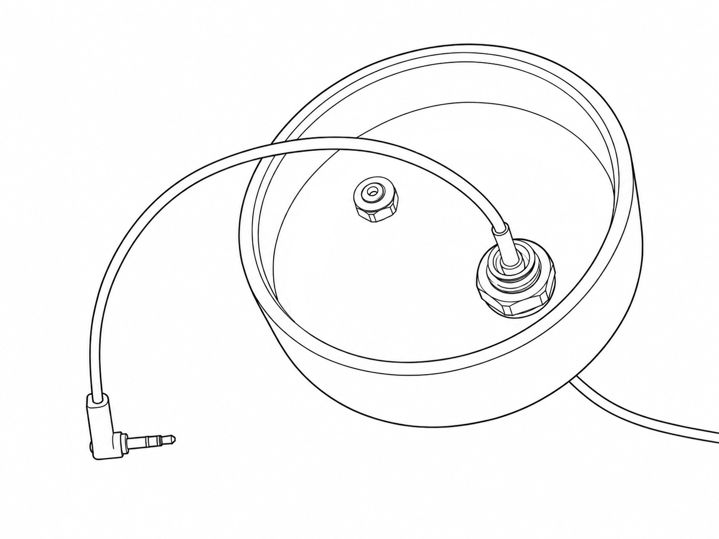
Plug the right-angle connector of the 20cm Flash Cable into the 3.5mm sync socket on the side of the Z Pro Flash.
4. Complete the connection to the PIR Motion Sensor v4
Remove the rubber plug from the PIR Sensor v4's signal socket and keep it safe for future use.
Plug in the 2.5mm male end of the Waterproof PIR Signal Cable into the signal socket of the PIR v4. Lock it in place by fastening the cable's lock nut onto the thread of the PIR v4 until the rear side of the lock nut pushes up into the rear side of the cable connector.