Assembling the Quick Deploy Frame
Before beginning assembly, lay out all Quick Deploy Frame components on a clear surface. The initial assembly requires the supplied 2.5 mm and 4 mm Hex Keys, plus an adjustable wrench or thin nose pliers (not supplied). Do not fit the camera housing, flashes or PIR motion sensor until the frame has been fully assembled and checked for stability.
1. Assemble the Main Frame
Place the Frame Base on a flat surface with the front of the Frame Base facing down.
As you are look down on the inside of the Frame Base, position the Left Bracket on the right-hand side of the Frame Base and the Right Bracket on the left-hand side.
Position the Frame Handle between the upper ends of the Frame Base and the Left and Right Brackets. The ends of the Frame Handle should sit on the inside of the Frame Base.
Use the twelve M4 10 mm Cap Head Screws and twelve M4 Nuts to fasten the Left Bracket and Right Bracket to the Frame Base and Frame Handle. The twelve fastening points are shown in the image below and they correspond to the twelve smaller-diameter holes in the frame parts. Tighten the fixings using the supplied 2.5 mm Hex Key and an adjustable wrench or thin-nose pliers to hold the nuts securely while you tighten the screws. Position the nuts on the inside of the frame - the screws should fasten inwards from the outside.
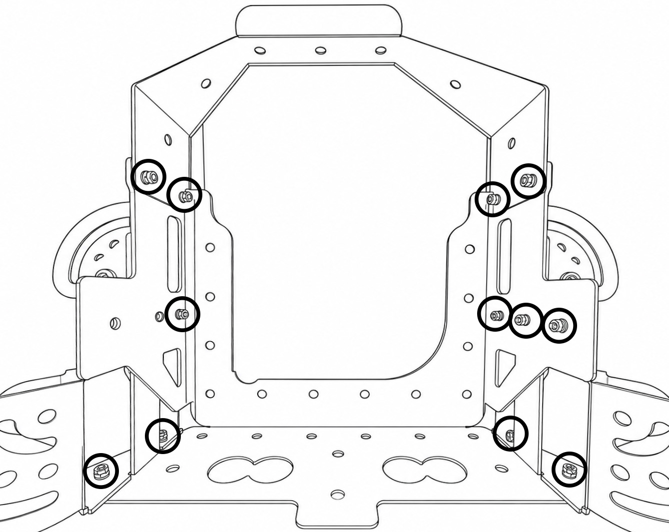
Check that the main frame is fully secure before continuing.
2. Fit the Legs
Push one Rubber Foot onto the end of each 300 mm Tube. It is recommended to push the Rubber Foot on at an angle rather than trying to squeeze both rubber lugs through at the same time. Make sure the rubber lugs are fully engaged and secure inside the tubes.
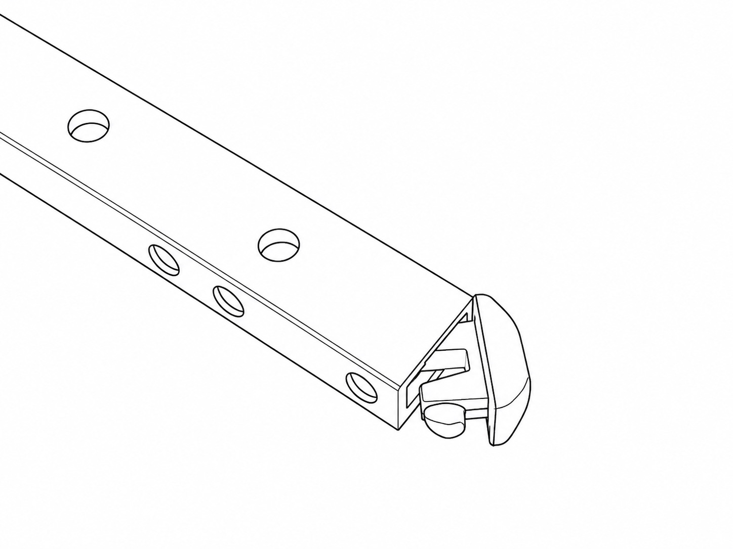
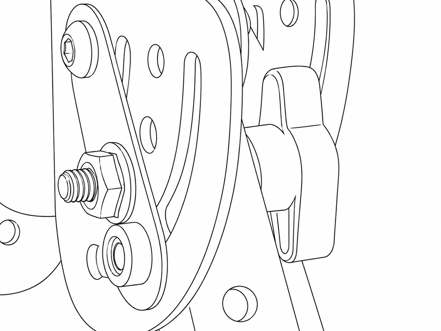
Attach two legs to the Left Bracket and two legs to the Right Bracket using the pivoting assemblies.
For each leg, use:
Fit each leg so that it can pivot outwards from the bracket. Tighten the Thumbscrew sufficiently to hold the leg in position while still allowing it to be adjusted during setup. The 1.25 Inch Button Head Screws should be kept loose enough that the leg can freely pivot around it, while the 1.25 Inch Thumbscrew is responsible for securing and clamping the leg in place.
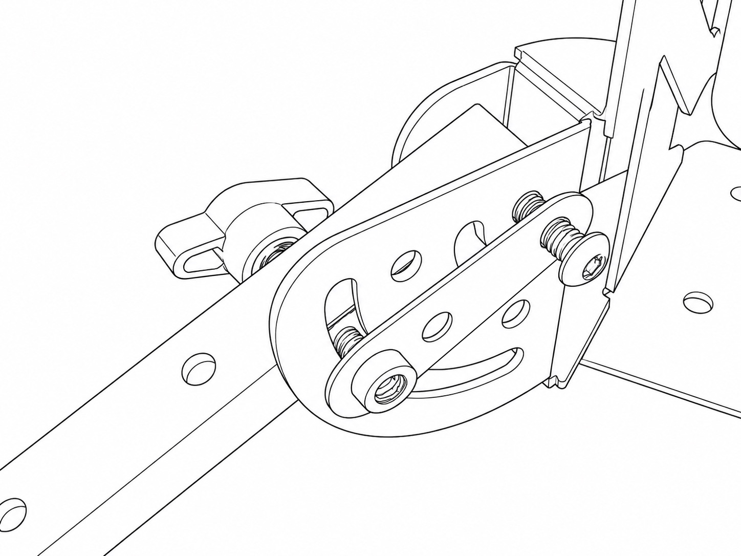
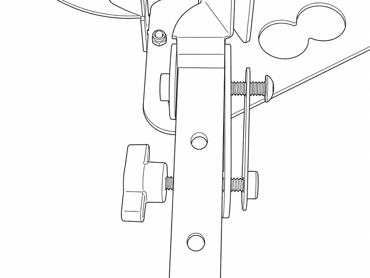
Repeat for all four legs.
Where a more rigid anti-slip assembly is required, fasten the 1.25 Inch Thumbscrews to the supplied Serrated Nuts through the pre-defined holes in the brackets and Friction Plates.
3. Fit the Flash Arms
Attach one 400 mm Tube to each side of the frame to create the two pivoting flash arms.
Use one 1.25 Inch Button Head Screw, one Friction Plate and one 1.25 Inch Thumbscrew for each arm.
Position the arms so that they can pivot independently away from the frame. Tighten the Thumbscrews enough to hold their position securely and keep the 1.25 Inch Button Head Screws loose enough that the arm can freely pivot when the Thumbscrew is released.
4. Fit the Mini Ball Heads
Attach one Mini Ball Head to the end of each flash arm using a 3/4 Inch Button Head Screw. These Mini Ball Heads will support the two Weatherproof Flash Housings.
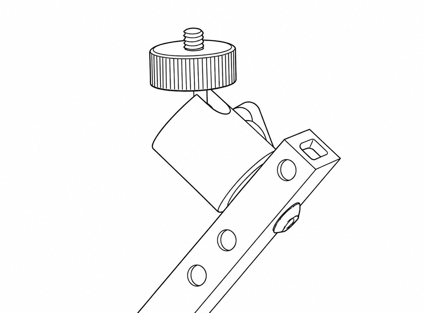
Attach the third Mini Ball Head to the Frame Handle using a 5/16 Inch Button Head Screw. This will support the PIR Motion Sensor v4.
Alternatively, the PIR Motion Sensor v4 Mini Ball Head may be mounted on a leg or flash arm using the remaining 3/4 Inch Button Head Screw, if this provides a more suitable sensor position.
Tighten the mounting screws using the supplied 4 mm Hex Key.
5. Final Frame Check
Before fitting the Camera Housing, Flash Housings and PIR Motion Sensor v4, check that:
* the Frame Base, Frame Handle and both Left and Right Brackets are securely fastened
* all four legs are stable and the Rubber Feet are properly fitted
* both flash arms are secure
* the Mini Ball Heads are securely fitted
* no components can move unexpectedly when the frame is lifted or adjusted.
Once assembled, the legs and flash arms can be repositioned in the field using the Thumbscrews.
Support the part being adjusted at all times, loosen only one fastening at a time, and retighten it fully before moving on to another adjustment.