
Controlling the Field of View
The field of view (FOV) of the Camtraptions PIR Sensor determines where an animal will be when the camera is triggered, making it a crucial part of composing your images—particularly for still photography. The field of view can be adjusted in several ways to precisely control the trigger zone.
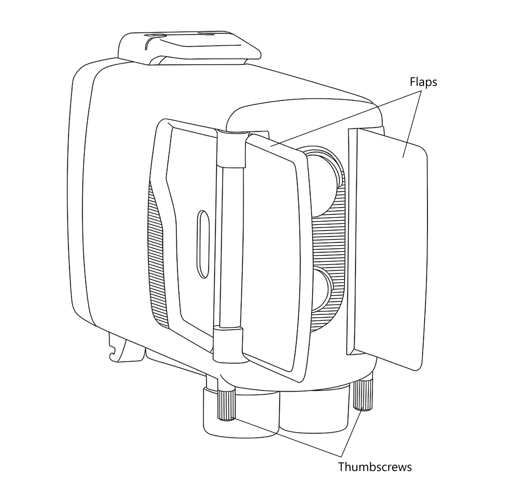
1. Using the Adjustable Side Flaps
Each side of the sensor is fitted with a flap or blinker that can be used to limit the field of view of the PIR sensors.
By folding the flaps outward, you can block unwanted detection zones to either side, ensuring that the sensor only triggers when an animal is directly in front of it.
To adjust the flaps:
- Loosen the thumbscrew on each flap.
- Rotate the flap into the desired position to restrict the field of view as needed.
- Tighten the thumbscrew again to hold the flap firmly in place.
For best results, ensure that both flaps are positioned symmetrically, with the sensor aimed at the centre of the intended trigger zone. The PIR elements are most sensitive in the middle of their field of view, so symmetrical adjustment helps ensure that the sensor receives the strongest possible signal.
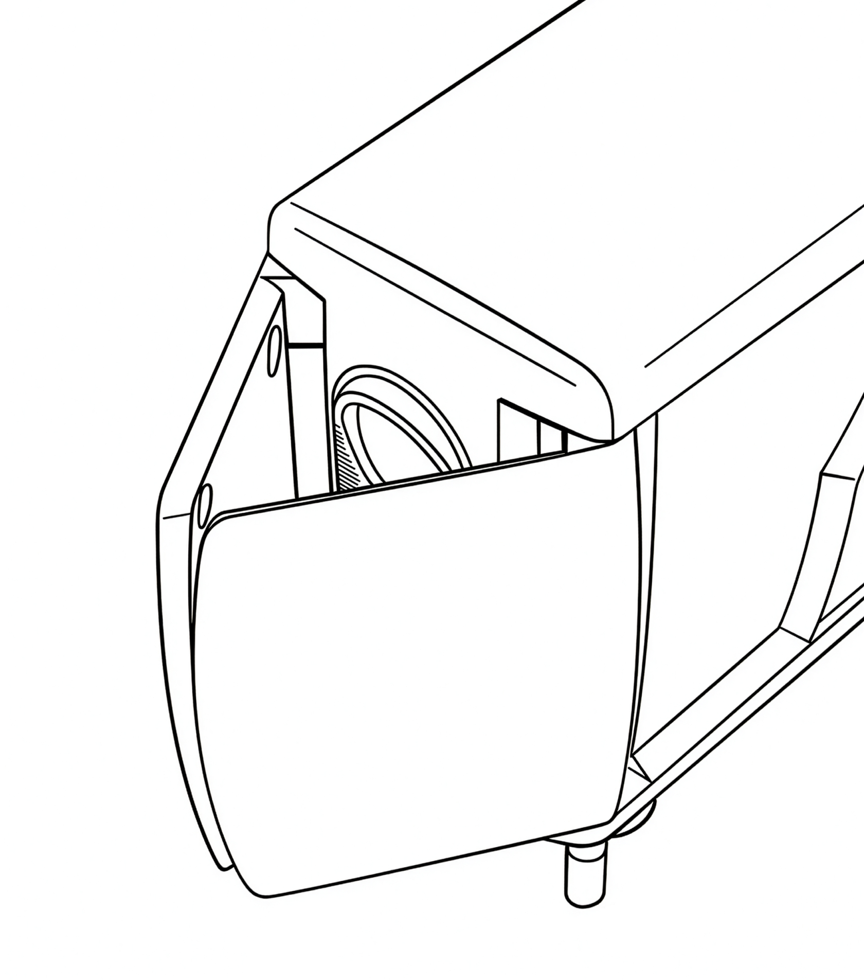
If you would like to reduce the field of view even further than the standard side flap positions allow, then you can undo the thumbscrews fully and swap the left and right flaps around. This makes it possible to achieve a very narrow angle resulting in an extremely precise trigger area.
Diagram showing flaps in reversed position:
2. Using the Dual-Sensor System
Version 4 includes two separate sensors, each with a different field of view:
- Wide sensor: approximately 60° horizontal field of view, 4.5° upward field of view, 13.5° downward field of view — shorter range but broader coverage.
- Far sensor: approximately 10° field of view (horizontal & vertical) — longer range but more precise detection area.
By adjusting the relative sensitivity of these two sensors, or disabling one entirely, you can fine-tune the spread and range of the trigger zone.
It should also be noted that Wide and Far sensors are both most sensitive to motion along the horizontal axis (sideways motion). They are less sensitive to upward/downward motion along the vertical axis.
3. Using the Indicator Light for Setup
One of the two front sensors includes a built-in red indicator light that can assist with setup. When the light is active, it briefly illuminates whenever motion is detected—helping you see exactly where the trigger zone begins and ends.
To use the indicator light:
- Turn on the sensor or press any button to activate setup mode.
- Walk or wave a hand in front of the sensor to observe where motion is detected.
- Adjust the sensor’s position or flap angles until the trigger zone aligns with your intended composition.
The indicator light remains active for five minutes after the last button press, after which it automatically disables to conserve power. For more details, see the Indicator Light section later in this manual.